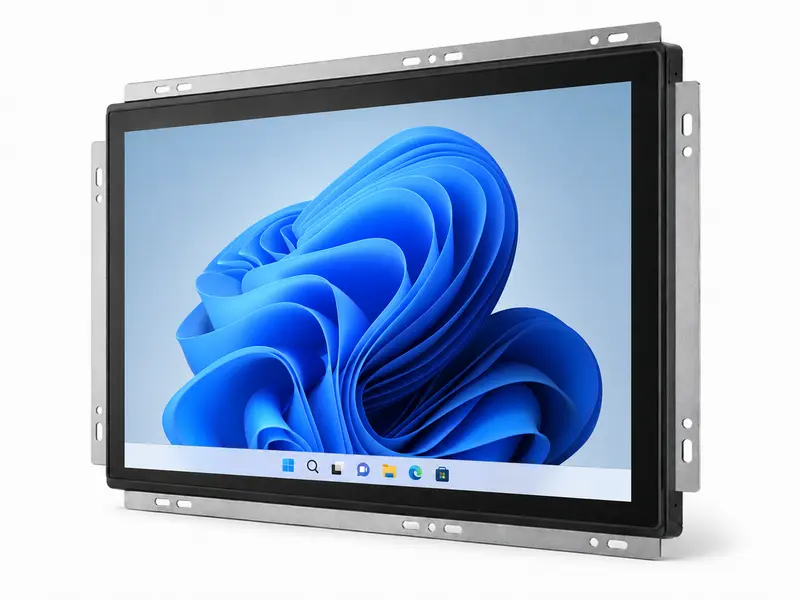
Monitor industrial de estrutura aberta para integração de equipamentos OEM
Conjuntos de monitores com estrutura aberta personalizados, concebidos para se adaptarem ao seu invólucro, controlador e requisitos de produção. Para quiosques, armários de máquinas, estações de carregamento de veículos elétricos, dispositivos de laboratório, terminais industriais e equipamentos HMI.
Monitores de estrutura aberta concebidos para se adaptarem ao design do seu equipamento OEM
Quando um monitor fechado padrão não cabe no seu equipamento, um monitor de estrutura aberta oferece um conjunto de ecrã pronto a integrar no seu próprio invólucro, painel de controlo, quiosque, estação de carregamento de veículos elétricos ou máquina industrial.
Cada unidade pode incluir o painel LCD, a placa controladora, a estrutura de montagem metálica, os cabos, o ecrã tátil e o vidro frontal. Isto ajuda a sua equipa de engenharia a evitar ter de adquirir e combinar componentes de visualização separados.
A Eagle Touch ajuda a adaptar o monitor de estrutura aberta à estrutura do seu equipamento, às entradas e saídas do controlador, à utilização do ecrã tátil, ao vidro frontal e ao plano de produção antes da construção da amostra.
É possível realizar amostras, testes-piloto e encomendas de pequenos lotes antes da produção em massa, a fim de verificar o encaixe mecânico, o funcionamento do ecrã, o desempenho do ecrã tátil opcional e o processo de montagem. Para outras estruturas de montagem, explore a nossa gama completa de monitores industriais e monitores tácteis.
Opções de configuração de monitores de estrutura aberta para projetos OEM
Comece por definir o tamanho do ecrã, a estrutura da caixa, a interface, a utilização tátil e o ambiente de trabalho. O Eagle Touch ajuda-o, em seguida, a confirmar a configuração do ecrã mais adequada ao projeto do seu equipamento.
- Tamanho do ecrã ou área visível
- Desenho recortado ou fotografia da habitação
- Modelo do comando ou entrada de vídeo preferida
- Requisitos relativos ao toque, ao vidro de proteção, ao brilho e ao ambiente
| Item de configuração | Opções típicas / Método de confirmação |
|---|---|
| Tamanho do ecrã | 7” - 32” |
| Resolução | Selecionados com base no tamanho do ecrã, na disponibilidade de ecrãs LCD e nos requisitos do projeto |
| Brilho | Opção padrão / de alto brilho / legível à luz solar |
| Tato | PCAP / resistivo / sem toque |
| Vidro de cobertura | Espessura, AG / AR / AF, impressão, tratamento das bordas |
| Ligação | Colagem a ar / colagem ótica |
| Estrutura mecânica | Montagem frontal / montagem traseira / estrutura de quadro definida pelo invólucro |
| Disposição dos cabos e conectores | Saída do cabo traseira/lateral, posição do conector, comprimento do cabo consoante o projeto |
| Entrada de vídeo | HDMI / VGA / DVI / DP (LVDS / eDP, consoante o projeto) |
| Interface tátil | USB / RS232 (I²C by project) |
| Entrada de energia | Adaptado à potência nominal do equipamento |
| Ambiente | Condições de funcionamento em ambientes interiores / semi-exteriores / definidas pelo equipamento |
| Controlo da produção | Especificações aprovadas e acompanhamento das revisões |
Precisa de um modelo inicial com base no tamanho? Consulte o nosso Lista de modelos de monitores táteis com estrutura aberta para configurações comuns de ecrãs táteis PCAP e resistivos, com tamanhos entre 7” e 32”.
Instale um monitor de estrutura aberta no invólucro do seu equipamento
No caso da integração em estrutura aberta, o tamanho do ecrã é apenas o ponto de partida. A abertura, a profundidade, os pontos de fixação, os conectores e a orientação dos cabos têm de corresponder ao projeto final do equipamento.
Exemplo de referência para o recorte, a montagem, a profundidade e a orientação do cabo.
Uma fotografia com as dimensões indicadas é, muitas vezes, suficiente para detetar precocemente riscos de inadequação.
É possível obter uma NDA antes de partilhar os desenhos pormenorizados do recinto.
O que deve ser verificado antes da compilação de teste?
Estes detalhes ajudam a evitar retrabalho no invólucro, interferência nos cabos e problemas de montagem após a construção da amostra do monitor.
Área de abertura e área visível
Verifique as dimensões da abertura, a sobreposição da moldura, a tolerância, a área ativa e a área visível antes de definir o projeto da caixa.
Instalação à frente ou atrás
Confirme a montagem frontal, a montagem traseira, a posição do suporte, os orifícios de montagem e o acesso para manutenção, de acordo com a sua caixa.
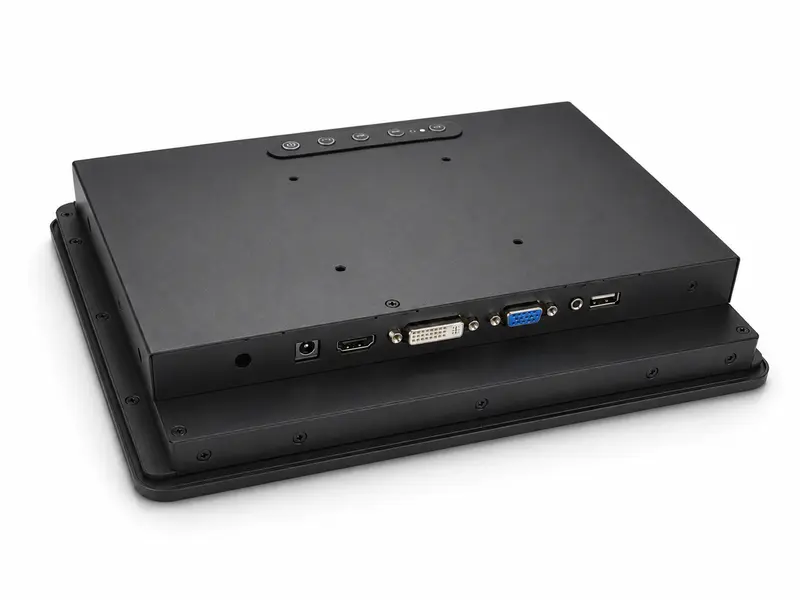
Despejo traseiro
Deixe espaço para o módulo LCD, a placa controladora, a altura do conector, a curvatura do cabo e a montagem final.
Orientação do conector e do cabo
Verifique a localização do conector, a direção de saída do cabo, o espaço disponível para o traçado e o alívio de tensão antes de iniciar a montagem da amostra.
Desenho com recorte ou fotografia da habitação com as dimensões assinaladas
Conceito de montagem, caso já tenha sido decidido
Limite de profundidade, espaço livre do conector ou restrição ao traçado do cabo
Adapte o monitor de estrutura aberta às entradas e saídas do seu controlador
Depois de o monitor se adaptar à caixa, o próximo risco prende-se com a compatibilidade do sinal, do ecrã tátil e da alimentação. O Eagle Touch ajuda a verificar a placa controladora, a entrada de vídeo, a comunicação tátil e a ligação de alimentação antes da construção de uma amostra.
- Sinal de vídeo: HDMI / VGA / DVI / DP (LVDS / eDP, consoante o projeto)
- Comunicação tátil: USB or RS232 for monitor integration; I²C can be evaluated for embedded touch-panel projects.
- Ligação à rede elétrica: adaptado à potência disponível do sistema e à disposição do equipamento
- Placa controladora: selecionado de acordo com o painel LCD, o sinal de entrada, a utilização do ecrã tátil e o espaço de instalação
Deve-se verificar o acesso às entradas/saídas do controlador, ao sinal tátil, ao trilho de alimentação e aos conectores antes de a amostra ser construída.
O toque, o vidro, o tratamento da superfície e a colagem devem ser selecionados de acordo com o ambiente de funcionamento final.
Opções de estrutura frontal para ecrãs táteis e vidro
Selecione o tipo de ecrã tátil, o vidro de proteção, o tratamento da superfície e o método de colagem consoante a forma como o equipamento será utilizado, limpo, visualizado e protegido.
Precisa apenas de um painel tátil ou de um vidro de proteção? Consulte a nossa soluções industriais para ecrãs tácteis.
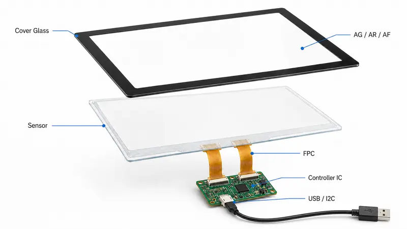
- Tátil PCAP: multitoque, utilização com luvas, vidro de proteção personalizado
- Ecrã tátil resistivo: entrada de pressão ou controlo antigo
- Sem contacto: equipamento apenas para visualização com comandos externos
- Vidro de cobertura: espessura, impressão, AG / AR / AF, acabamento das bordas
- Ligação: colagem a ar ou ótica, para facilitar a leitura e garantir a proteção
Aplicações de monitores de estrutura aberta em equipamentos OEM
Os monitores de estrutura aberta são utilizados quando o ecrã tem de ser integrado no invólucro do cliente, na estrutura da máquina, no armário, no quiosque ou no terminal, em vez de funcionar como um monitor externo independente.
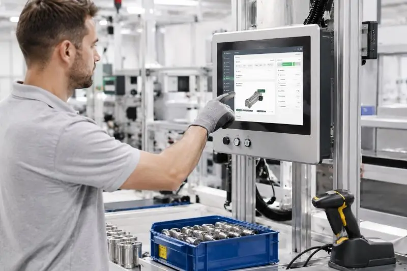
Armários de automação e controlo
Interfaces de visualização integradas para painéis de controlo de máquinas, armários industriais, postos de operação, sistemas HMI de fábrica e equipamentos de monitorização de processos.
Pontos-chave: montagem fixa, ajuste por recorte, operação com luvas, passagem de cabos, interface do controlador e fornecimento contínuo a longo prazo.
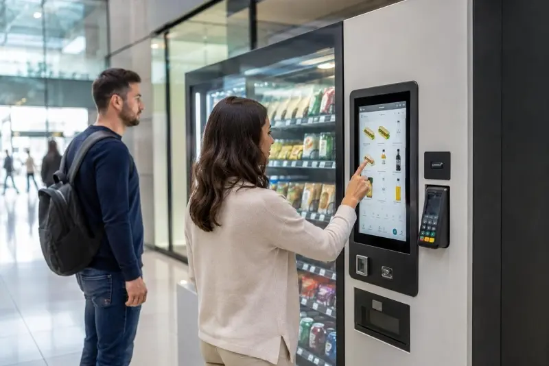
Quiosques, terminais de retalho e de autoatendimento
Ecrãs táteis de estrutura aberta para quiosques de emissão de bilhetes, terminais de check-in, máquinas de pagamento, máquinas de venda automática, sistemas de ponto de venda e terminais de encomendas.
Pontos-chave: utilização por toque pelo público, vidro de proteção, instalação compacta, proteção frontal, acesso para manutenção e longas horas de funcionamento.
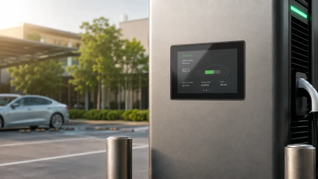
Carregamento de veículos elétricos e terminais exteriores
Conjuntos de ecrãs para estações de carregamento de veículos elétricos, terminais de pagamento ao ar livre, equipamentos energéticos, infraestruturas públicas e interfaces de controlo semi-exteriores.
Pontos-chave: brilho, vidro frontal, ligação ótica, intervalo de temperatura, conceção da vedação e fornecimento estável para a implementação do projeto.
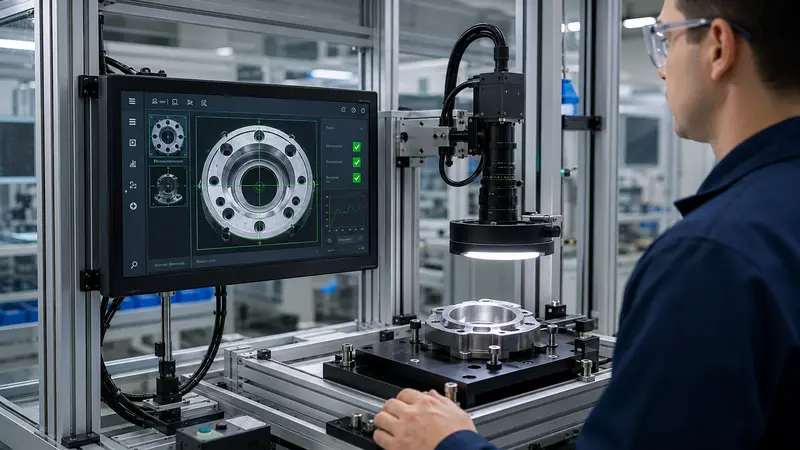
Sistemas de Laboratório, Inspeção e Medição
Ecrãs incorporados para analisadores de laboratório, instrumentos de diagnóstico, estações de visão artificial, bancadas de medição, sistemas de ensaio e equipamento de inspeção.
Pontos-chave: ajuste do invólucro, interface estável, visibilidade da imagem, condições de limpeza, clareza ótica e montagem repetível.
Estrutura aberta, montagem em painel ou montagem VESA?
Escolha a estrutura do monitor com base no método de instalação, no design da caixa e no acesso para manutenção — e não apenas no tamanho do ecrã.
Monitor de quadro aberto
Ideal para caixas de quiosques, caixas de máquinas e equipamentos OEM, em que o ecrã se integra no projeto mecânico do cliente.
Escolha esta opção quando for necessário integrar o monitor na sua própria caixa, sem uma caixa autónoma completa.
Monitor para montagem em painel
Ideal para armários de controlo, painéis de comando, consolas industriais e painéis frontais de equipamentos.
Escolha esta opção quando o monitor necessitar de uma moldura frontal ou de uma estrutura montada no painel para instalação na parte frontal.
Monitor de montagem VESA
Ideal para ecrãs junto às máquinas, suportes de parede, braços, suportes e instalações em postos de trabalho.
Escolha esta opção quando o monitor puder ser montado externamente, em vez de ser integrado no invólucro ou no painel frontal.
Para a instalação no painel frontal, consulte o nosso soluções de monitores para montagem em painel. Para instalação em suporte, braço ou parede, consulte o nosso Opções de monitores com suporte VESA.
Concebido para se adaptar. Testado para envio. Controlado para garantir a repetição da produção.
O seu monitor de estrutura aberta deve caber na caixa, ser compatível com o controlador e manter a consistência nas encomendas repetidas.
A Eagle Touch controla o projeto desde a revisão da configuração até à validação das amostras, à inspeção da remessa e à produção em série.
Envie um desenho, uma fotografia da caixa, uma fotografia das entradas e saídas ou uma lista de requisitos.
Configuração confirmada antes da amostra
O tamanho, o recorte, a montagem, a profundidade, a saída do cabo, a interface, o ecrã tátil, o brilho e a entrada de alimentação são verificados antes da montagem.
Ajuste real, funcionalidade real
As unidades de amostra permitem verificar o encaixe mecânico, a saída do ecrã, a resposta ao toque, a compatibilidade dos sinais, a ligação de alimentação e a montagem.
Verificado antes do envio
São analisados a imagem do ecrã LCD, o ecrã tátil, a entrada de vídeo, a alimentação, a montagem da moldura, o aspeto, a disposição dos cabos, as etiquetas, a embalagem e a documentação.
Estável para encomendas recorrentes
A produção em série segue a configuração aprovada. Qualquer alteração no ecrã LCD, na moldura, no controlador, no ecrã tátil, na interface ou na estrutura é analisada previamente.
Ficheiros do projeto:
Desenho, fotografia, E/S, especificações
Âmbito da inspeção:
Ecrã, toque, alimentação, montagem
Conformidade:
CE, FCC, RoHS, REACH, consoante o âmbito da encomenda
Perguntas frequentes sobre monitores de estrutura aberta
Questões fundamentais a ter em conta antes de selecionar, testar ou integrar um monitor de estrutura aberta em equipamento OEM.
Vamos discutir as suas necessidades
Partilhe a sua candidatura, os seus requisitos ou o desafio que enfrenta atualmente. A nossa equipa irá analisar os detalhes e recomendar uma solução prática para avançar.