Custom Industrial Display Design for OEM Systems
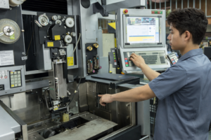
Introduction In industrial equipment, the display subsystem is part of a broader human-machine interface (HMI) and …
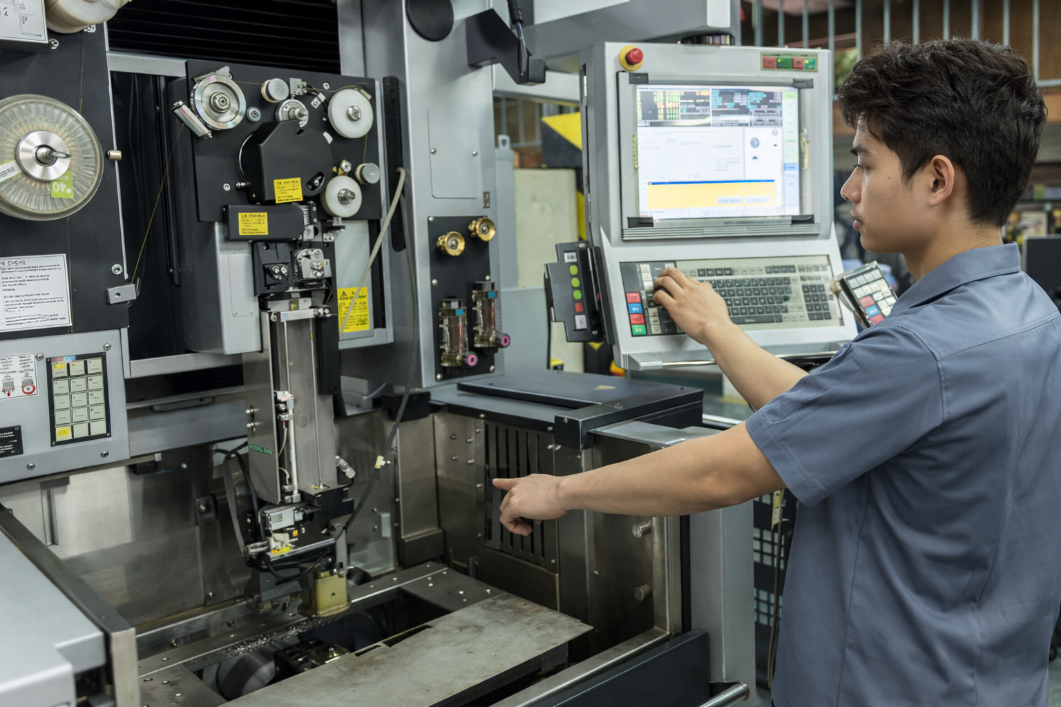
In industrial equipment, the display subsystem is part of a broader human-machine interface (HMI) and must operate reliably under defined environmental, electrical, and mechanical constraints.
Standard display modules are typically designed for controlled environments. Industrial deployments introduce additional variables such as wide temperature ranges, vibration, airborne contaminants, and extended service lifecycles. Under these conditions, a generic display can become a system reliability risk.
A custom industrial display design approach allows the display subsystem to be engineered in alignment with system-level requirements, including optical performance, electrical interface compatibility, mechanical integration, and lifecycle planning.
In most OEM systems, the display should be treated as part of the control system architecture rather than a standalone module.
A custom industrial display is engineered to match a specific equipment architecture, rather than adapted from a general-purpose product.
Customization typically spans four layers:
Optical layer
Display engine
Interface layer
Mechanical integration
Unlike standard industrial monitors, this approach allows the display to be directly integrated with embedded control platforms such as panel PCs or SoC-based systems, reducing conversion layers and improving system stability.
Panel selection directly impacts viewing behavior, power consumption, and long-term stability.
| Parameter | TN | IPS | VA |
|---|---|---|---|
| Viewing angle | Narrow | Wide | Moderate |
| Contrast | Low | Moderate | High |
| Response time | Fast | Moderate | Slower |
| Cost | Low | Medium | Medium |
IPS panels are commonly selected for industrial HMIs due to consistent color and viewing angle performance.
However, IPS panels typically require higher backlight power, which must be considered in sealed or thermally constrained designs.
Backlight design is a primary determinant of both visibility and service life.
Key parameters:
In field deployments, backlight lumen decay is often the dominant failure mechanism rather than LCD panel degradation.
Engineering considerations:
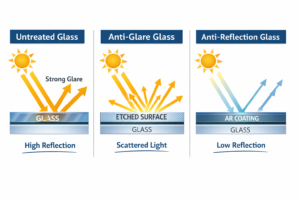
Optical bonding replaces the air interface between the LCD and cover glass with an optically clear adhesive.
| Aspect | Air Gap | Optical Bonding |
|---|---|---|
| Reflection | Higher | Lower |
| Sunlight readability | Reduced | Improved |
| Mechanical rigidity | Lower | Higher |
| Field repairability | Easier | More complex |
Optical bonding is typically required when:
Projected capacitive (PCAP) touch performance is highly dependent on system tuning rather than hardware alone.
Key variables:
Design trade-off:
Controller firmware tuning and grounding design are critical to stable operation.
Display interface reliability is influenced by system-level electrical design.
Common interfaces:
Practical consideration:
LVDS is often preferred in industrial environments due to its tolerance to longer cable lengths and EMI exposure, even though it offers lower bandwidth compared to eDP.
Typical risks:
Mitigation:
Displays are frequently deployed in sealed enclosures with limited airflow.
Key heat sources:
Typical approach:
Passive cooling via chassis conduction is commonly used.
Industrial deployments introduce combined stress conditions:
Design responses:
Mechanical integration affects both durability and optical performance.
Key decisions:
Critical risks:
Tolerance control across the stack-up is essential.
Industrial systems typically require 7–10+ years of availability.
Risks:
Mitigation strategies:
Service strategy should be defined during system design.
Modular approach
Integrated bonded module
Selection depends on deployment accessibility and service cost model.
Customization is appropriate when system constraints cannot be met using standard products.
Typical triggers:
A custom design may not be appropriate when:
Custom industrial display design is a system-level engineering decision rather than a component selection task.
It enables alignment between optical performance, electrical integration, mechanical constraints, and lifecycle requirements. However, it also introduces additional complexity in design and supply chain management.
The decision should be based on total system impact, with emphasis on long-term reliability, maintainability, and integration stability.
1. What is the most common failure point in industrial displays?
Backlight degradation is more common than LCD failure, particularly under high brightness operation.
2. How much brightness is required for outdoor use?
Typically 800–1500 nits, depending on ambient light and optical bonding.
3. Is optical bonding always required?
No. It is mainly required for high ambient light or high humidity environments.
4. How can EMI issues be reduced?
Use shielded cables, proper grounding, and controlled impedance routing.
5. What lifecycle should be targeted?
Industrial systems typically require 5–10+ years of component availability.
6. How should display reliability be validated before mass production?
Thermal cycling, high-brightness aging, and EMC testing are commonly used to validate long-term stability.
Introduction In industrial equipment, the display subsystem is part of a broader human-machine interface (HMI) and …

Introduction In industrial equipment design, the human-machine interface (HMI) directly affects system usability, reliability, and maintenance …

Introduction Human-machine interfaces (HMIs) are now standard components in modern industrial equipment. Displays allow operators to …
Introduction Industrial displays are frequently deployed in environments where lighting conditions are difficult to control. Equipment …
Send your application details. We respond with configuration direction and next steps.