Custom IK10 Touchscreens for Kiosks, EV Chargers and Public Equipment
Vandal-resistant PCAP touchscreens, LCD touch modules, and complete touch monitors engineered around the final enclosure, mounting structure, and touch requirements.
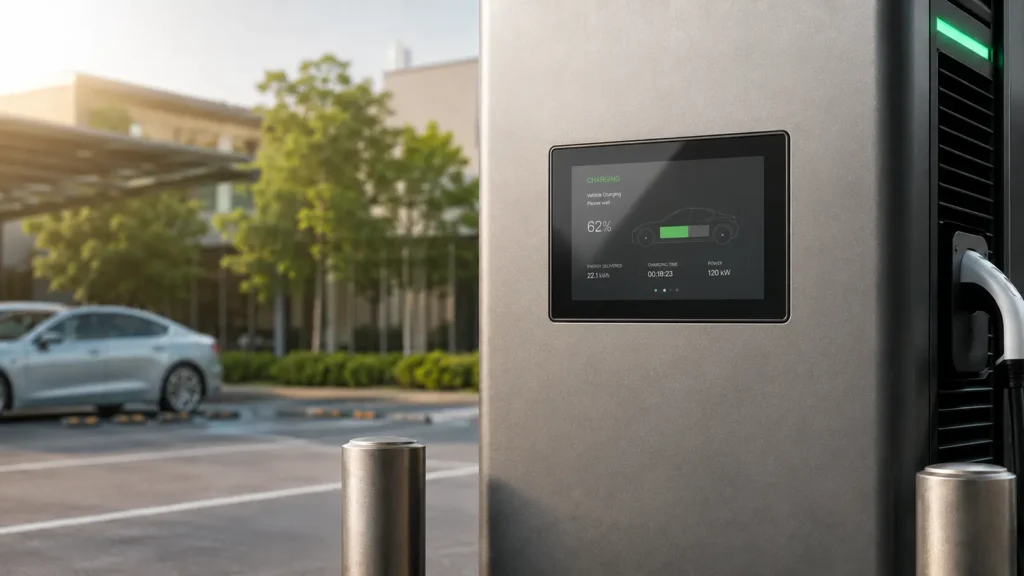
Custom IK10 Touchscreen Solutions for OEM Equipment
IK10 corresponds to a 20 J external mechanical impact level under IEC/EN 62262—commonly referenced as a 5 kg mass dropped from 400 mm. It is specified for vandal-resistant touchscreen designs used in unattended or publicly accessible equipment, where the front surface may face accidental impact, rough use, or deliberate damage.
Eagle Touch designs and manufactures custom IK10 PCAP touchscreens, LCD touch modules, and complete touch monitors. Our project experience includes EV chargers, kiosks, payment terminals, ticketing machines, children’s play equipment, and other public-use systems.
Each project is developed to the customer’s drawing and enclosure. The IK10 structure is reviewed in its intended mounting condition before sampling, with engineering support continuing through sample validation and production launch.
IK10 Touchscreen Configuration Range
Check the main product, touch, display, and mechanical options available for your project. Final specifications are confirmed against the drawing, enclosure, operating environment, and required test method.
| Configuration Area | Available Options |
|---|---|
| Product Scope and Impact Requirement | |
| Product Format | PCAP touch panel / LCD touch module / open-frame touch monitor / panel-mount touch monitor |
| Size Range | 10.1″–65″; standard and custom outlines reviewed by project |
| Impact Target | IK10 / 20 J under IEC/EN 62262; final verification based on the assembled structure, mounting condition, and agreed test method |
| Touch and Optical Configuration | |
| IK10 Cover Glass | Thickness selected for the complete IK10 structure; 6 mm used in representative projects. Custom outline, holes, cut-outs, border printing, logo, and edge finish. |
| PCAP Controller | EETI / ILITEK, selected to match the cover-glass stack, LCD noise, touch requirements, and operating environment |
| Touch Interface | USB / I²C / RS232 |
| Touch Performance | Multi-touch; glove operation and water-rejection tuning by project |
| Bonding | Air bonding / OCA optical bonding / OCR optical bonding |
| Surface Options | AG / AR / AF / anti-UV options, black border printing, logo, and custom glass finish |
| Display and Electrical Configuration | |
| LCD Options | Customer-specified or project-selected LCD; standard or high brightness, required resolution, viewing angle, and wide-temperature options |
| Monitor Interface and Power | HDMI / DisplayPort / VGA / DVI; DC 12 V, DC 24 V, or wide-voltage input by project |
| Mechanical Integration and Validation | |
| Mechanical Integration | Custom enclosure opening, support area, gasket space, mounting holes, brackets, assembly clearance, and cable routing |
| Environmental Protection | Front IP65 / IP66 integration options; outdoor use, sunlight, UV exposure, temperature, and condensation reviewed separately |
| Project Validation | Drawing review, sample validation, touch tuning, and third-party IK testing support |
IK08 vs IK09 vs IK10: Which Rating Does Your Project Need?
These are the impact levels most often considered for public-use touch equipment. The bars compare their impact energy on a 0–20 J scale. Selection should be based on access, credible impact risk, and the consequences of failure—not on outdoor use alone.
IK08 Touchscreen
Approximately 1.7 kg from 300 mm
Protected or partly controlled equipment
Where occasional accidental impact is possible but exposure to public misuse is limited.
IK09 Touchscreen
Approximately 5 kg from 200 mm
Public or semi-public equipment
Where stronger accidental impact or a moderate risk of misuse is expected.
IK10 Touchscreen
Approximately 5 kg from 400 mm
Unattended public equipment
Where heavy impact or deliberate damage is credible and field replacement is costly.
IEC/EN 62262 classifies the impact protection provided by an enclosure. The values above are energy references; formal verification uses the applicable IEC 60068-2-75 hammer method on the assembled structure in its specified mounting condition—not on the cover glass alone. IP sealing, sunlight readability, UV exposure, and operating temperature are separate requirements.
IK10 Performance Depends on the Final Assembly
IK10 performance is determined by the complete front assembly, not by cover-glass thickness alone. Support geometry, gasket compression, and bonding affect mechanical performance; grounding and controller tuning affect touch stability.
Eagle Touch reviews the customer’s drawing and intended mounting condition before sampling to identify risks that may not appear when the touch panel is tested on its own.
IK10 · 20 J Impact Test
Edge Stress and LCD Pressure
Uneven support or excessive gasket compression can stress the glass edge and cause LCD pressure marks, light leakage, or touch drift after assembly.
Electrical Noise and False Touch
LCD or power-system noise, inadequate grounding, and unsuitable cable routing can reduce sensitivity or cause false or erratic touch events. Controller settings are tuned to the final stack and electronics.
Water Rejection and Glove Operation
When required, water rejection and glove operation are checked with the final cover glass, bonding stack, sealing design, and controller configuration.
IK10 Touch Solutions Across Indoor and Outdoor Equipment
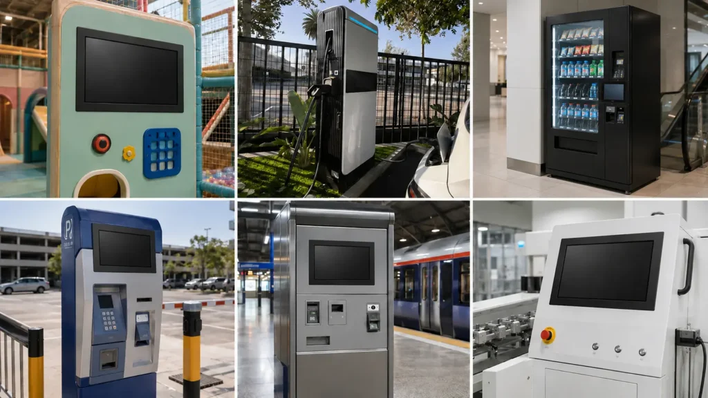
Eagle Touch has supplied custom IK10 touch displays across a range of indoor and outdoor OEM equipment. Representative projects include 15″ and 27″ reinforced displays for children’s play equipment, 10.1″ and 15.6″ high-brightness outdoor displays for EV chargers, and a 23.8″ impact-resistant indoor monitor. These projects have involved thick cover glass, stable PCAP touch, outdoor sealing, display readability, and equipment-specific integration—practical experience we apply when reviewing new OEM requirements.
What to Send for an IK10 Project Review
You do not need a finished specification before contacting us. A drawing, application photo, or basic size requirement is enough for an initial review.
Application and Environment
Tell us what equipment the touchscreen will be used in, whether it is indoors or outdoors, and the expected impact or vandal risk.
Drawing or Main Dimensions
Send the mechanical drawing if available, or provide the required screen size, front opening, visible area, and available mounting space.
Display and Touch Requirements
Share any known requirements for brightness, resolution, display interface, touch interface, glove use, water rejection, or optical bonding.
Quantity and Project Stage
Let us know the sample quantity, estimated production volume, current project stage, and expected schedule.
Start with What You Have
Send a drawing, enclosure sketch, current display model, or application photo. We will identify the missing details and recommend the appropriate custom touch solution, including the glass, PCAP, bonding, sealing, and display structure.
Complete drawings are helpful, but not required for the first discussion.
IK10 Touch Screen FAQ
Common questions about customizing, integrating, and validating an IK10 PCAP touch solution for OEM equipment.
Start with Your Drawing or Basic Requirements
Tell us the equipment, target size, installation environment, and expected quantity. Send a drawing if available; if not, an enclosure sketch, application photo, or current display model is enough for an initial review.
We can review the IK target, cover glass, PCAP, LCD, bonding, touch interface, sealing, and mounting structure as one complete OEM solution.