How Industrial Touch Screens Work and How to Select the Right Technology

Quick Answer: How Industrial Touch Screens Work Industrial touch screens detect input using pressure (resistive), capacitance …
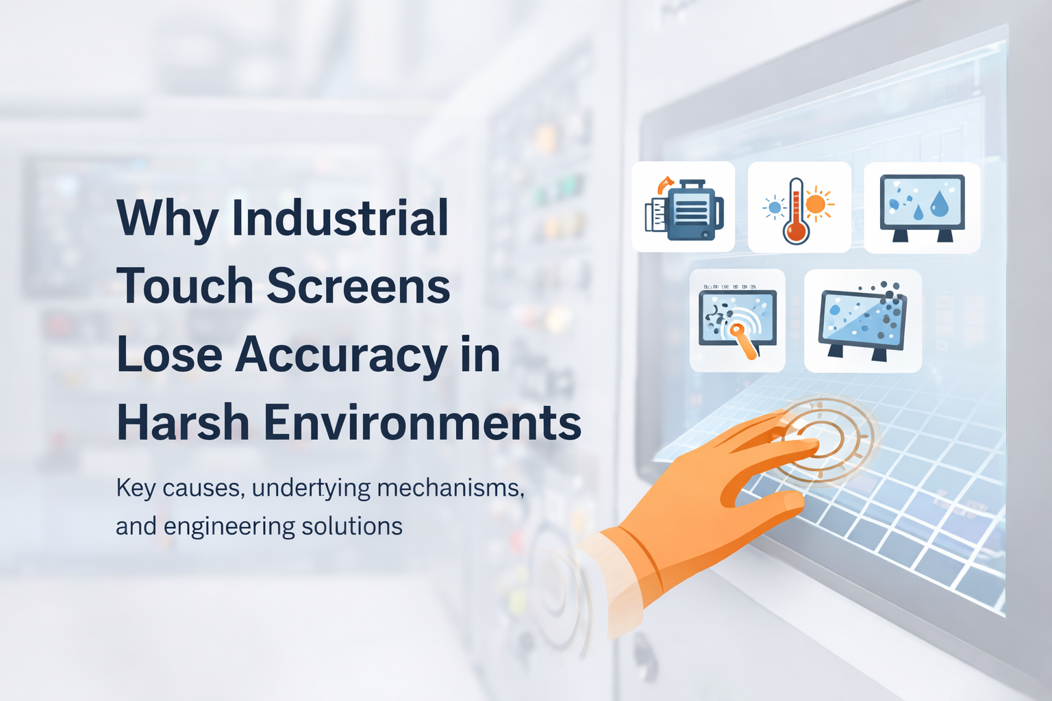
Touch accuracy degradation is a recurring issue in industrial HMI systems. Unlike consumer devices, industrial touch interfaces operate in environments with electrical noise, temperature variation, mechanical stress, and long duty cycles.
For OEM engineers and system integrators, touch accuracy directly impacts usability, safety, and operational efficiency. A misregistered input is not just inconvenient—it can lead to incorrect machine operation, downtime, or safety risks.
A broader understanding of industrial touch system design is covered in this industrial touch screen technology guide.
This article explains why industrial touch screens lose accuracy—and how to prevent it through system-level engineering and supplier selection.
Industrial touch screens lose accuracy due to:
These factors disrupt signal detection—especially in PCAP systems—leading to coordinate errors, delayed response, or false inputs.
In many industrial projects, touch accuracy issues are frequently misinterpreted as hardware defects.
In practice, the root cause is often system-level EMI or grounding design, not the touch panel itself. Replacing the panel without addressing electrical conditions typically does not resolve the issue.
In real installations, systems that perform normally in lab conditions may fail when deployed near variable frequency drives (VFDs) or high-current switching equipment due to differences in grounding and noise coupling.
What this means for your system:
If touch issues appear intermittently, analyze electrical and grounding conditions before replacing hardware.
Touch accuracy refers to how precisely a touch interface maps a physical input point to a digital coordinate.
Most industrial systems use Projected Capacitive (PCAP) technology, which relies on stable electrostatic field sensing across a conductive grid.
From a signal perspective, accuracy depends on maintaining a stable signal-to-noise ratio (SNR). Any disturbance can reduce SNR, shift baseline capacitance, and result in coordinate errors.
Typical integrations include:
Each integration introduces different constraints in grounding, enclosure design, and EMI exposure.
A conductive electrode matrix detects capacitance changes.
External noise can introduce parasitic capacitance and distort mutual capacitance signals.
Engineering implication:
Sensor design must maintain sufficient signal margin under noisy conditions.
The controller samples signals and calculates touch coordinates.
Under EMI, noise may cause:
Engineering implication:
Industrial controllers use adaptive filtering and dynamic thresholds to maintain stability.
Optical bonding removes the air gap between layers.
Engineering implication:
Noise sources include:
Noise coupling paths:
Engineering implication:
Firmware manages filtering and detection logic.
Engineering implication:
Balanced tuning is required.
EMI reduces signal-to-noise ratio and introduces instability in capacitance sensing.
Engineering implication:
Leads to intermittent and difficult-to-reproduce failures.
Temperature affects capacitance values and material expansion.
Engineering implication:
Without compensation, systems exhibit touch drift over time.
Causes deformation and misalignment.
Engineering implication:
Non-bonded structures degrade faster in industrial environments.
Water, oil, and dust interfere with sensing.
Engineering implication:
Requires sealing and firmware compensation.
Reduces capacitance change.
Engineering implication:
Requires sensitivity tuning and controller support.
Material aging and electrical changes occur over time.
Engineering implication:
Requires drift compensation and lifecycle validation.
| Scenario | Risk | Recommended Solution |
|---|---|---|
| Factory Automation | High EMI | Shielded PCAP + industrial controller |
| Outdoor Systems | Temperature + moisture | Optical bonding + sealing |
| Food Processing | Water + contamination | Waterproof design + filtering |
| Public Terminals | Heavy usage | Durable glass + stable controller |
1. Controller Quality
Industrial-grade, EMI-optimized
2. EMI Capability
Test data and compliance
3. Optical Bonding
In-house, validated
4. Environmental Support
Glove, water, temperature
5. Long-Term Stability
Drift control and lifecycle design
Suitable:
Not suitable:
👉 In these cases, resistive touch may be more stable.
Industrial touch screen accuracy depends on electrical, mechanical, and environmental conditions.
Reliable performance requires system-level design, including signal integrity, mechanical stability, and environmental adaptation.
EMI from industrial equipment is the most common cause, especially in poorly grounded systems.
Yes, by improving signal stability and reducing vibration impact.
Partially. It cannot solve hardware or EMI-related problems.
It causes capacitance drift and inconsistent response.
In harsh environments, yes—but with lower usability.
Due to material aging and electrical drift.
Test in real operating conditions—not just lab environments.
Controller type, EMI testing, bonding, environmental support, and drift control.
If your application involves EMI, temperature variation, or harsh environments, touch performance should be evaluated based on actual operating conditions.
Provide key parameters such as:
This enables accurate evaluation before deployment
Quick Answer: How Industrial Touch Screens Work Industrial touch screens detect input using pressure (resistive), capacitance …

Introduction Touch accuracy degradation is a recurring issue in industrial HMI systems. Unlike consumer devices, industrial …
Introduction In industrial equipment, a touch interface is not only a user input layer—it is a …
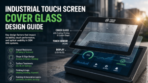
Introduction In industrial HMI systems, cover glass is the outermost interface between the user and the …
Send your application details. We respond with configuration direction and next steps.