What Is an Industrial Panel PC? Components, Types and Applications
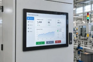
An industrial panel PC is a computer with a built-in display, usually a touchscreen, designed for …
Eagle Touch Engineering Team
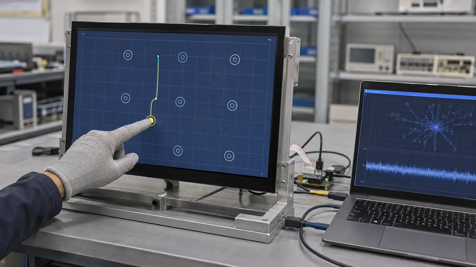
An industrial touch screen that misses gloved input does not always need “more sensitivity.” A screen that produces false touches is not necessarily too sensitive either.
For a projected capacitive (PCAP) touch screen, sensitivity depends on the complete system: cover glass, sensor, controller, firmware, grounding, power supply and operating environment. Increasing sensitivity without identifying the real problem may improve glove response while creating ghost touches around water or electrical noise.
This guide explains what can be adjusted, what cannot, and how to tune an industrial PCAP touch screen without confusing sensitivity with calibration.
Yes, if the touch controller and firmware support adjustment.
Most industrial USB PCAP screens do not have a universal sensitivity control in Windows. Windows calibration mainly maps the physical touch position to the displayed image. It normally does not change the raw capacitive signal, glove response or water rejection.
PCAP sensitivity is usually adjusted through:
EETI, ILITEK, Goodix and other controllers do not share one adjustment method. Available parameters also vary by controller model and firmware version. Identify the exact controller and save the original configuration before making changes.
Correct diagnosis matters more than the setting itself.
| What you observe | What it usually means | Correct action |
|---|---|---|
| Cursor appears away from the touch point | Coordinate mapping or display-orientation issue | Calibrate or check the installation |
| Light finger touches are missed across the screen | Insufficient usable touch signal | Check signal margin before increasing sensitivity |
| Finger works but the required glove does not | Glove signal is below the detection margin | Apply or tune a glove profile |
| Touch is detected before the finger reaches the glass | Sensitivity is too high or hover is enabled | Reduce sensitivity or adjust the threshold |
| Random touches appear near a motor, inverter or noisy supply | Electrical interference | Correct the noise source; do not raise sensitivity |
| One fixed area never responds | Sensor, FPC, assembly or controller-channel fault | Inspect the hardware |
| Every point works but response is slow | Filtering, firmware, operating system or application delay | Measure latency instead of assuming low sensitivity |
If the screen is completely unresponsive, start with our industrial touch screen not responding checklist. For a consistent cursor offset, use the touch screen accuracy guide instead.
Do not complete PCAP tuning on a loose sensor and assume the same settings will work in the finished equipment. The enclosure, LCD, power supply, grounding and nearby electronics can all affect the signal seen by the controller.
Use the final production stack whenever possible:
Record the original behavior before changing anything. Test bare-finger input, the production glove, edges, corners, dragging and required multi-touch functions. Note whether the problem changes at maximum LCD brightness or when nearby equipment is switched on.
Check the controller-board label, IC marking, USB device information or product documentation. Confirm the exact controller model and firmware version.
A utility or parameter file intended for another controller may display the wrong settings or write an incompatible configuration. For OEM equipment, obtain the approved tool and parameter file from the touch screen supplier rather than using an unverified public download.
Before adjustment, export the existing settings or retain the original firmware. Record the controller model, firmware version, sensor revision and cover-glass stack so stable operation can be restored if necessary.
“The touch is not sensitive” is not enough information for tuning. Define exactly what fails:
Parameter names differ between controllers, but PCAP tuning may include:
Change one group, apply the configuration and repeat the same test. Restart or power-cycle the unit when required by the controller.
Do not copy numerical settings from another screen size or sensor design. A stable value for a 7-inch sensor may be unsuitable for a 21.5-inch sensor, even when both use the same controller family.
For bare-finger operation, use enough sensitivity to achieve reliable response across the active area without unnecessary hover or false input.
For glove operation, test the exact production glove. Material, thickness, fit and contact area all matter. A profile that works with thin nitrile gloves may fail with insulated work gloves. Increasing gain or lowering the detection threshold may help, but glove performance also depends on the sensor pattern and controller capability.
If glove input is a design requirement, see our industrial glove-compatible touch screen guide for sensor and controller selection.
Weak touch response and high noise both reduce usable signal margin. A higher-sensitivity setting may work on a test bench but cause ghost touches after installation in the final machine.
Test with the production power supply, grounding, enclosure and LCD brightness. If the behavior changes when a motor, relay, inverter or charger operates, stop increasing sensitivity and investigate the interference source.
Use the touch screen interference test guide for that diagnosis. Firmware tuning cannot compensate for poor grounding, an unsuitable power supply or severe conducted noise.
As cover glass becomes thicker, the touch signal generally becomes weaker. However, there is no universal 6 mm or 8 mm limit for every industrial PCAP screen.
The practical limit depends on:
The final cover glass, sensor and controller must therefore be tested as one system. If sufficient signal margin cannot be achieved without false touches, the correct solution may be a different sensor or controller rather than more aggressive tuning.
Stop tuning and inspect the hardware or integration when:
Firmware cannot repair a damaged electrode or eliminate noise caused by poor system integration.
Validate the new configuration in the finished unit, not only with several taps on a dry test bench.
The goal is not the highest possible sensitivity. It is reliable detection of the intended input with enough margin to reject water, electrical noise and accidental contact.
Usually not through a standard Windows setting. Windows calibration mainly corrects coordinate mapping. Raw PCAP sensitivity normally requires a controller-specific utility, firmware configuration or supplier-provided profile.
No. Calibration can correct the difference between the physical touch point and cursor position. It does not normally increase the capacitive signal through thick glass or gloves.
Only after testing the actual glove and final cover glass. A glove profile may improve detection, but excessive sensitivity can also increase false touches from moisture or electrical noise.
The new setting may be detecting noise, moisture or hover input as a valid touch. Restore the previous configuration and check the power supply, grounding, cable routing and operating environment.
For an effective evaluation, provide the controller model, sensor drawing, cover-glass thickness, bonding stack, required glove type, power supply, enclosure grounding and a video showing the symptom.
Eagle Touch can determine whether the problem requires parameter tuning, improved system integration or a different sensor and controller combination.
An industrial panel PC is a computer with a built-in display, usually a touchscreen, designed for …
An embedded PC is a computer configured to work as part of a machine or larger …
Start with the software the panel PC must run and the conditions it must fit. Then …
Choosing an industrial panel PC IP rating starts with two questions: what dust and water exposure …
Share your application, requirements, or current challenge. Our team will review the details and recommend a practical way forward.