What Is an Industrial Panel PC? Components, Types and Applications
An industrial panel PC is a computer with a built-in display, usually a touchscreen, designed for …
Eagle Touch Engineering Team
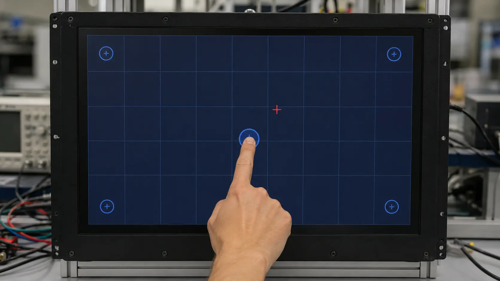
When an operator touches one button but the HMI activates another, the touch screen is not necessarily defective. The error may come from display mapping, screen rotation, calibration data, mechanical pressure or the way the host application converts touch coordinates.
The first step is not repeated calibration. It is identifying the error pattern.
A consistent offset usually points to mapping or calibration. Random movement points in a different direction—normally power, grounding, electrical noise or an unstable touch signal.
This guide covers industrial touch screens that respond, but report the wrong position. If the LCD image is normal and there is no touch response at all, use our industrial touch screen not responding checklist. If the cursor jumps, clicks by itself or changes when nearby equipment starts, follow the touch screen interference test.
Run a full-screen touch test before changing any settings. Draw slow horizontal and vertical lines across the screen, then tap the center and four corners. Test with the same finger, glove or stylus used in the actual application.
| What you see | Most likely direction |
|---|---|
| The reported point is displaced by the same distance and direction everywhere | Display mapping or calibration offset |
| Left becomes right, top becomes bottom, or the axes are exchanged | Rotation, axis inversion or coordinate transform error |
| The center is accurate but the error increases toward the edges | Incomplete calibration, incorrect scaling or resistive-touch linearity |
| Only one fixed area is inaccurate | Local pressure, sensor damage, electrode fault or contamination inside the assembly |
| The trace is irregular or jumps while the finger moves smoothly | Power noise, grounding, EMI, cable coupling or controller tuning |
| Touch works on the bench but changes after mounting | Bezel pressure, enclosure contact, grounding or final-system integration |
| Touch is weak rather than displaced | Sensitivity issue, not coordinate calibration |
This separation matters. Recalibration can correct a coordinate transform; it cannot repair a damaged sensor or remove electrical noise.
A touch controller reports an X-Y coordinate. The operating system or embedded application then maps that coordinate to a position on the displayed image. Accurate operation requires these two coordinate systems to agree.
An offset can therefore originate at three levels:
If the pointer is correct in the operating system but wrong only inside one HMI application, the touch hardware is unlikely to be the first suspect. Test outside the application before replacing any part.
A properly integrated PCAP touch screen is normally configured at the factory and does not require routine user calibration. In Windows systems, many USB PCAP controllers operate as standard HID touch devices.
When a PCAP screen shows a fixed offset, first check:
Do not assume that every PCAP accuracy problem can be solved with the Windows calibration tool. Some PCAP controllers should use their factory configuration or the controller manufacturer’s utility instead.
Resistive touch screens depend more directly on a calibration matrix that converts the controller’s raw values into display coordinates. Recalibration may be required after a controller, computer, operating system or display orientation is changed.
Four-wire resistive screens can also develop increasing edge error as the flexible conductive layer wears. Five-wire resistive designs generally maintain coordinate stability better because position measurement is based mainly on the glass substrate, but they still require the correct controller and calibration data.
This is the first check for a computer with two or more displays. A touch monitor can show the correct image while its touch input is assigned to another screen.
Use the operating system’s display-identification function or the controller manufacturer’s utility to map each touch device to its intended monitor. Disconnecting the other monitor temporarily is also a useful comparison test.
If the problem affects the entire screen by a consistent amount, do this before opening the enclosure.
Confirm the following:
Normal operating-system DPI scaling should not create a physical offset in a correctly implemented HID touch application. However, older or custom HMI software may calculate touch positions incorrectly after resolution or scaling changes. If the fault appears in only one program, compare it with a basic drawing or touch-test application.
Before recalibrating, save the existing controller settings if the utility allows it. Then use the method specified for that touch technology and controller.
During calibration:
If the same offset returns immediately after a successful calibration, stop repeating the procedure. The cause is probably mapping, configuration, mechanical assembly or hardware rather than missing calibration data.
Uneven bezel force, a trapped FPC, adhesive buildup or metal contact near the active area can distort touch behavior. Test the same unit in two conditions:
If a fixed local error appears only after assembly, loosen the mounting force evenly and inspect the perimeter, FPC route and rear structure. Do not solve the problem by repeatedly changing controller sensitivity; remove the mechanical condition first.
A controller may communicate normally over USB or I²C while using parameters intended for a different sensor size, channel layout, cover-glass stack or orientation.
This is especially relevant after:
Confirm the sensor part number, controller model, firmware version and configuration file as one matched set.
Electrical noise normally produces jitter, broken lines, random coordinates, false touches or a problem linked to a motor, inverter, relay, charger or power supply. It does not usually create one perfectly repeatable offset across the entire screen.
If the trace is unstable, compare a known-good independent power supply, a short direct touch cable and a clean bench setup. Change one condition at a time. The complete isolation procedure is covered in our touch screen interference guide.
Where possible, perform an A/B comparison:
If the fault follows one touch assembly, investigate its sensor, controller, cable and configuration. If the fault stays with the machine, investigate host mapping, software, power, grounding and mechanical installation.
Calibration is unlikely to solve the issue when:
At that stage, replacement or supplier-level configuration may be more effective than another calibration attempt.
Accuracy should be verified on the complete equipment, not only on a loose sample.
Before mass production:
Optical bonding may improve display readability and mechanical integration, but it is not a substitute for correct coordinate mapping, controller configuration or calibration.
A clear test record shortens the diagnosis considerably. Provide:
Eagle Touch can review the sensor, controller, firmware, cable, host mapping and mechanical installation as one system. For an OEM project, send us the test video and configuration details before changing multiple components. A controlled comparison usually finds the cause faster than repeated replacement.
Normally, no. A correctly configured PCAP system should maintain its coordinate mapping without routine calibration. Recalibration or remapping may be needed after changing the host, display layout, orientation, firmware or controller configuration.
Increasing error toward the edges can indicate incomplete calibration, an incorrect transform, resistive-screen non-linearity or mechanical stress near the perimeter. Test before and after loosening the assembly to separate calibration from pressure.
Yes, but EMI normally produces unstable or changing coordinates rather than one fixed offset. Random movement should be investigated as an interference problem; a repeatable offset should be checked as a mapping or calibration problem first.
The displayed image and touch coordinate system may not have been rotated together. Check the operating-system orientation, touch mapping and any application-level transform.
No. Optical bonding does not correct an incorrect calibration matrix, display mapping or coordinate transform. Diagnose those items directly.
An industrial panel PC is a computer with a built-in display, usually a touchscreen, designed for …
An embedded PC is a computer configured to work as part of a machine or larger …
Start with the software the panel PC must run and the conditions it must fit. Then …
Choosing an industrial panel PC IP rating starts with two questions: what dust and water exposure …
Share your application, requirements, or current challenge. Our team will review the details and recommend a practical way forward.