Industrial LCD Backlight Technologies: How to Choose the Right Solution for Your Application
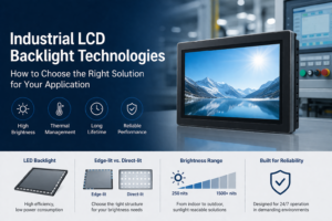
Introduction Industrial LCD backlight design directly determines display visibility, thermal performance, and long-term reliability. While LCD …

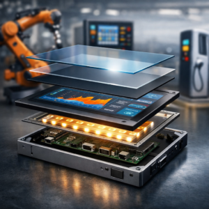
Industrial display structure directly affects system performance, reliability, and lifecycle cost in OEM equipment.
Unlike consumer displays, industrial display modules are designed for:
For engineers and procurement teams, understanding industrial display structure and its components helps ensure appropriate specification without unnecessary cost.For a broader overview of how displays are selected in real systems, including interface types, enclosure design, and mounting considerations, refer to our guide on industrial display monitors.
This guide explains how structure influences:
An industrial display structure is the layered assembly that forms a complete display module for embedded or OEM systems.
Typical layers include:
These layers are configurable rather than fixed. Selection depends on:
Each layer contributes to system-level behavior, including visibility, thermal performance, and long-term reliability.
Function: Image generation
Engineering impact:
Engineering note:
Excessive brightness increases power consumption and accelerates thermal stress on the backlight system.
Function: User input interface
Engineering impact:
Engineering note:
Controller tuning (sensitivity, noise filtering) is often more critical than touch technology selection in industrial environments.
Function: Optical coupling between layers
Engineering impact:
Engineering note:
Bonding is generally required for outdoor or high-humidity environments.
Function: Provides illumination for the LCD
Engineering impact:
Engineering note:
Backlight design (LED quality, thermal path) has a stronger impact on reliability than panel brand.
Function: Structural protection and mounting interface
Engineering impact:
Engineering note:
Aluminum enclosures improve thermal performance but increase weight and manufacturing cost.
| Scenario | Recommended Structure |
|---|---|
| Outdoor / direct sunlight | High brightness + optical bonding |
| Indoor HMI | Standard brightness + air gap |
| High humidity | Optical bonding + sealed structure |
| Cost-sensitive system | Air gap + standard panel |
| Harsh industrial environment | Bonded display + metal enclosure |
This mapping helps align structural configuration with actual operating conditions.
Display cost is primarily influenced by structural configuration:
Engineering insight:
Over-specification—especially in brightness and bonding—is a common source of avoidable cost. In many OEM projects, simplifying the display structure can reduce total system cost by 20–40% without affecting functionality.
Key parameters:
Bonded and sealed structures provide improved stability in harsh environments.
Thermal design directly affects reliability:
Typical approaches:
Industrial applications often involve:
This requires rigid mounting design and mechanically stable display assemblies.
Industrial displays must interface with:
Integrated panel PC architectures can reduce system complexity and wiring requirements.
Key point:
Structural design determines real-world performance more than individual component specifications.
Industrial display structures are widely used in:
These applications require a balance of durability, visibility, and integration stability.
Use a fully engineered display structure when:
A full industrial configuration may not be necessary when:
Industrial display structure determines how a display performs under real operating conditions.
Selection should be based on:
A structured selection approach helps avoid unnecessary cost while maintaining required reliability.
Choosing the wrong display structure often leads to unnecessary cost or long-term reliability issues.
Share your application details with us:
We’ll suggest a configuration that balances performance, reliability, and cost—without over-specification.
1. Which component most affects display lifetime?
The backlight system is typically the primary limiting factor for operational lifespan.
2. Is optical bonding required for all applications?
No. It is mainly required for outdoor or high-humidity environments.
3. Can structure be customized for OEM integration?
Yes. Most industrial display modules are configurable based on mechanical and electrical requirements.
4. Does higher brightness always improve usability?
No. It improves visibility in high ambient light but increases thermal and power demands.
Introduction Industrial LCD backlight design directly determines display visibility, thermal performance, and long-term reliability. While LCD …
Introduction Industrial display structure directly affects system performance, reliability, and lifecycle cost in OEM equipment. Unlike …
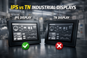
IPS vs TN — Which should you choose? Choose IPS for: multi-angle viewing, outdoor environments, touch-based …

Introduction Can a commercial LCD display be used in industrial equipment to reduce cost? This is …
Send your application details. We respond with configuration direction and next steps.