What Is an Industrial Panel PC? Components, Types and Applications
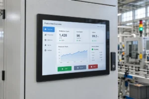
An industrial panel PC is a computer with a built-in display, usually a touchscreen, designed for …
Eagle Touch Engineering Team
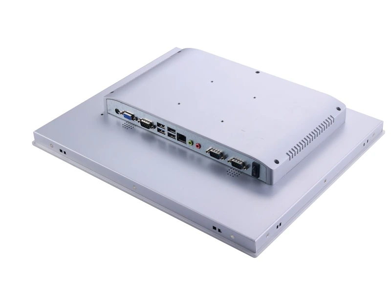
A specification such as “4 × USB, 2 × LAN, 2 × COM” looks straightforward. It still leaves several questions unanswered: can both COM ports operate as RS485, can the USB ports power all connected peripherals, and will the application communicate with the PLC?
Choose panel PC I/O ports by listing the devices they must connect to first. Then confirm the electrical interface, communication requirements, software support and installation space. This gives you a usable configuration to check against a quotation and test on a sample.
List each external device by model and quantity. Include permanently connected equipment and anything technicians need during maintenance.
| Connected device | Possible interface | First detail to confirm |
|---|---|---|
| PLC | Ethernet, RS232 or RS485 | PLC model and supported communication method |
| Barcode scanner or printer | USB, serial or Ethernet | Exact peripheral model and driver requirements |
| Meter or instrument | RS232, RS485 or Ethernet | Protocol, wiring and isolation requirements |
| Industrial camera | USB or Ethernet | Bandwidth, power and simultaneous camera count |
| Switch or status signal | Suitable digital I/O | Signal voltage and input/output characteristics |
| Factory or service network | Ethernet | Network arrangement and independent port requirements |
These are possible connections, not interchangeable options. Use the device documentation to establish what is required.
A panel PC typically runs the operator interface and exchanges data with controllers and peripherals. Its available ports do not, by themselves, make it a replacement for a PLC or safety controller.
Ethernet can connect a panel PC to PLCs, network printers, cameras and plant systems. Check the required link speed and any network-controller requirements specified by the application vendor.
Two independent LAN ports may be useful when the machine network and factory network need separate connections. They do not automatically provide secure separation: routing, bridging and access rules still need appropriate configuration.
For Ethernet cameras, confirm whether power comes from a separate supply, a PoE switch or a supported PoE port. An ordinary LAN port does not provide PoE power.
Choose the serial standard required by the connected device. RS232 commonly serves point-to-point connections; RS485 is frequently used for differential serial buses. RS422 may be required by particular instruments or existing equipment.
“Two COM ports” is not a complete specification. Confirm each port’s supported modes, how the mode is selected, and its connector pinout. Identical D-sub connectors can carry different signals.
For RS485, check two-wire or four-wire operation, isolation needs and the bus wiring arrangement. Follow the equipment documentation for termination and biasing; adding resistors indiscriminately can overload the bus. Texas Instruments explains the conditions in its RS485 termination guide.
USB commonly connects scanners, printers, readers, cameras and storage devices. Check bandwidth and available power per port and across shared groups, especially when several devices operate together.
A scanner may work on its own but disconnect when other peripherals are added. Check the available USB power and shared controller resources before assuming that every socket can support the same load. Cameras also need sufficient bandwidth, particularly when several operate together.
The panel PC’s built-in touch connection is normally handled internally. Count external USB ports against external equipment and maintenance needs.
For CAN equipment, confirm the CAN controller and transceiver, connector wiring, software API and required higher-layer protocol. CAN hardware alone does not establish application compatibility.
For digital signals, distinguish general-purpose GPIO from industrial DI/DO. Check voltage thresholds, isolation, input type and output current. A logic-level GPIO must not be connected directly to a 24 V signal or relay coil unless the specified interface circuitry supports it.
If the project needs a second display, confirm the available HDMI or DisplayPort output, supported resolution and simultaneous display configuration. For USB-C, check the actual functions provided: the connector shape does not establish video output or charging capability.
Once the hardware connection is defined, check how the devices exchange data.
For example, an RS485 meter using Modbus RTU needs more than matching wires. The application must support Modbus RTU, use the correct serial settings and device address, and read the correct register map. The Modbus Serial Line Guide describes the protocol and implementation requirements.
Likewise, an Ethernet connection to a PLC needs compatible communication software. Do not assume that a LAN port supplies every industrial Ethernet protocol or the required runtime licence.
Check drivers, SDKs and application support against the exact operating system and processor architecture. A peripheral demonstrated on Windows may require different support on an Android or Linux platform. Resolve this before hardware approval; our panel PC operating system guide covers the broader OS decision.
Count connections used at the same time, then add any justified maintenance or expansion allowance.
The following is an illustrative requirement list, not a standard configuration:
| Project requirement | Configuration to evaluate |
|---|---|
| One Ethernet PLC connection | One LAN port |
| Separate factory network connection | A second independent LAN port with suitable network configuration |
| One USB scanner and one USB printer | Two simultaneously usable USB ports with adequate power |
| One RS485 instrument | One correctly configured RS485 port; isolation as required |
| Local USB service access | An additional accessible USB port |
Check the connector layout with the actual plugs. D-sub hoods, right-angle adapters and cable bends can consume more space than expected. Allow access to fastening screws and enough room to replace a cable without removing the entire computer.
Provide strain relief where cables could pull on connectors. If the rear connections are exposed to water or dust, evaluate the complete connector-and-cable sealing arrangement. A front IP rating does not establish protection for rear ports. Review the panel PC mounting options alongside the I/O drawing.
A qualified converter or hub can be practical, but adds another component to power, secure and validate. Internal expansion also depends on the slot’s electrical support, module dimensions, drivers and available connector openings.
Test the proposed sample with the intended peripherals, cables and the intended application software. A successful connection on the bench is only the first check.
Record the approved hardware revision, port assignments, serial modes, drivers and software image. Include any converters and cable assemblies. This gives repeat orders and future servicing a defined configuration to follow.
Only if that port is specified for both modes. Some ports are fixed; others switch through BIOS, software or hardware settings. Confirm the mode-selection method and pinout for the chosen model.
No. The application must support the PLC’s communication method. Confirm the PLC model, software driver or runtime, network settings and any licensing requirements.
Sometimes. External adapters and internal modules may help, but compatibility, power, space and software support must be checked. Define known requirements before approving the platform.
Send your peripheral models and quantities, required interfaces and protocols, operating system, application requirements, and available installation space. Include pinout drawings, cable lengths and isolation requirements where relevant, plus sample quantity and expected production volume.
Send Eagle Touch your connected-device list, operating system requirements and installation drawing. We can review available industrial panel PC configurations, identify requirements that need customization and clarify which connections need sample testing. If the port list is not final, the device list is enough to start the discussion.
An industrial panel PC is a computer with a built-in display, usually a touchscreen, designed for …
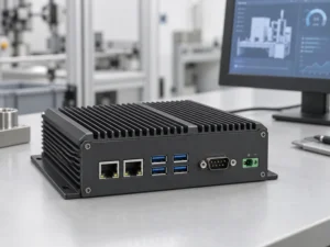
An embedded PC is a computer configured to work as part of a machine or larger …
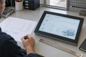
Start with the software the panel PC must run and the conditions it must fit. Then …
Choosing an industrial panel PC IP rating starts with two questions: what dust and water exposure …
Share your application, requirements, or current challenge. Our team will review the details and recommend a practical way forward.