What Is an Industrial Panel PC? Components, Types and Applications
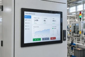
An industrial panel PC is a computer with a built-in display, usually a touchscreen, designed for …
Eagle Touch Engineering Team
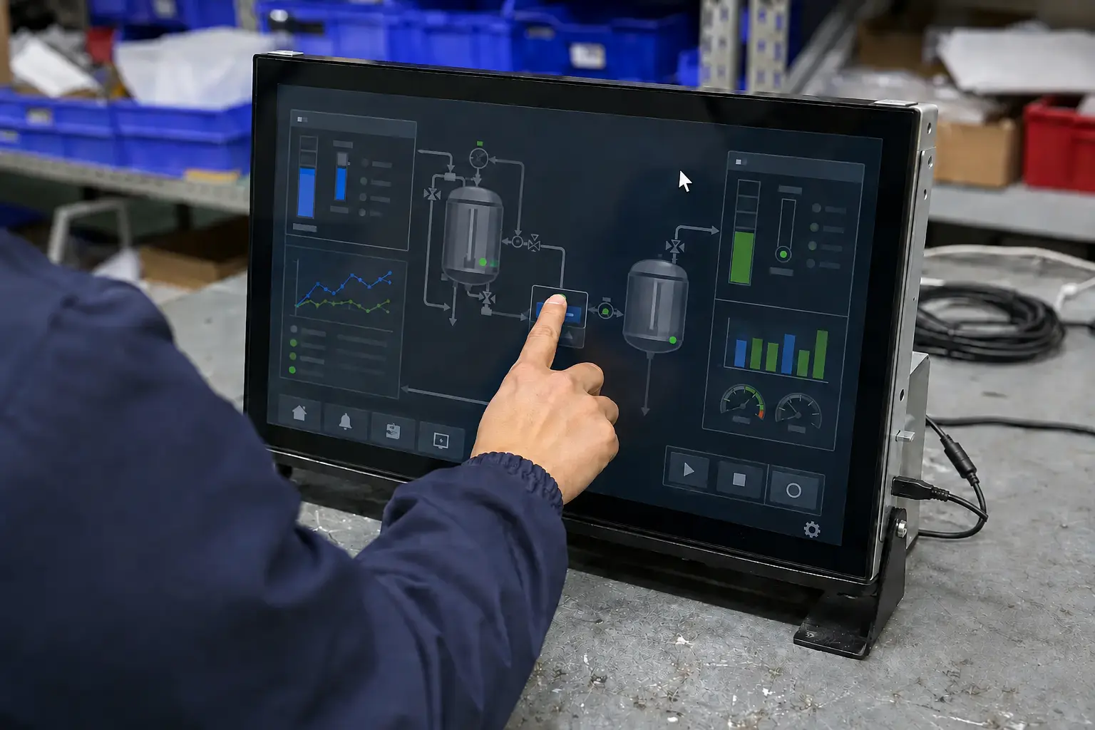
Ghost touches do not always mean the touch panel is defective.
In industrial equipment, a PCAP touch screen may work perfectly on the bench but develop ghost touches, jumping coordinates, missed touches or an unstable response after installation. When that happens, the fault is often outside the touch panel: power noise, an uncontrolled ground-potential difference, cable coupling, mechanical pressure or the surrounding equipment.
The most useful diagnostic rule is simple:
If the problem appears only after the touch screen is installed, test the complete system before replacing the panel.
This guide shows how to isolate the cause one condition at a time.
Interference does not always cause total touch failure. Typical symptoms include:
These symptoms are clues, not proof. Water, excessive mounting pressure, a damaged FPC, incorrect controller settings or a faulty sensor can produce similar behaviour. When the failure appears is often the best clue.
| When the problem appears | First area to investigate |
|---|---|
| When a motor, inverter, relay or charger starts | Radiated or conducted electrical noise |
| Only with the final power supply | Power quality or common-mode noise |
| After moving or extending the touch cable | Cable coupling, shielding or signal integrity |
| Only after installation in the enclosure | Grounding, cable routing or mechanical pressure |
| After water reaches the surface | Wet-touch performance or controller tuning |
| Always in the same physical area | Sensor, FPC, controller or assembly damage |
A power supply can provide the correct nominal voltage and still create a touch problem. Switching noise, excessive ripple, poor transient response or common-mode noise can disturb the controller’s electrical reference.
If the touch becomes stable with a known-good independent supply, investigate the original power source and its connection to the system.
PCAP controllers detect very small changes in capacitance. An uncontrolled voltage difference between the controller, host, display chassis and equipment structure can reduce the available signal margin.
Grounding must follow the intended equipment design. Protective earth, chassis ground, USB shield and signal ground are not automatically interchangeable. Do not add ground wires or connect all ground points together at random; an incorrect connection can create a ground loop or compromise electrical safety.
USB, I²C and touch-controller FPC cables carry low-level signals. Long cables and poorly planned routes can pick up noise from:
Start by separating the cables. Select shielding, ferrites or filtering only after the coupling path is understood.
Motors, variable-frequency drives, chargers, relays, contactors and radio transmitters may introduce conducted or radiated noise. A strong time correlation is important: if ghost touches begin when one device switches on and stop when it switches off, that device or its wiring path becomes a clear suspect.
Not every post-installation fault is EMI. Uneven sensor pressure, metal contact near the active area, a trapped FPC or a distorted cover can also cause unstable touch behaviour.
Cover-glass thickness does not generate EMI. However, thicker glass reduces touch signal strength. If the controller was not tuned for the final glass, bonding stack and enclosure, the system may have less noise margin and become more sensitive to the surrounding electrical environment.
Change only one condition at a time. If the power supply, cable, grounding and controller settings are all changed together, the screen may improve but the root cause will remain unknown.
Before disconnecting anything, note:
Record a short video with a touch-test utility. A visible coordinate trace is more useful than saying “the touch is unstable.”
Remove the display assembly from the equipment, or test an identical assembly on a clean bench. Use the same host and software first.
If the fault remains unchanged, inspect the touch panel, FPC, controller, USB connection, driver and firmware. If it disappears, the final machine or installation condition is involved.
Power the display and touch system from a stable, correctly rated independent source. Keep the original supply disconnected during this comparison.
If the screen becomes stable, do not immediately specify a larger adapter. The problem may be ripple, switching noise, grounding or the way the power supply is integrated, rather than insufficient wattage.
Replace extension cables and hubs with a short, known-good direct connection. Confirm that connectors are fully seated and that the cable shield has not been damaged.
If a short cable works but the production cable does not, investigate its quality, length, routing and shield termination before changing the panel.
Temporarily move the touch cable away from power modules, motor wiring, backlight wiring, LVDS/eDP cables and high-current conductors. Do not bundle touch and power cables together for a neat appearance.
If the symptom changes when the cable moves, noise coupling is likely. Establish the route first; then determine whether additional shielding, ferrites or filtering is necessary.
Operate nearby motors, relays, chargers, contactors, radios and inverters one at a time while watching the touch-test screen.
A repeatable on/off relationship is stronger evidence than a random failure. Record which device was operating, its load condition and how quickly the touch problem appeared.
With the equipment safely de-energized, inspect the specified chassis bonding, protective-earth connection, cable shields and touch-controller mounting. Check for loose fasteners, painted contact surfaces where a bonded connection was intended, and unplanned connections at multiple points.
Any powered measurement or change to protective earth, chassis bonding or signal ground should be handled by a qualified engineer using the equipment schematic and touch-controller guidance.
Add the enclosure, production power supply, final cables and nearby loads back one at a time. Test after every change.
The step that makes the problem return is usually close to the cause.
| Test result | What it suggests | What to check next |
|---|---|---|
| Stable on the bench, unstable in the machine | Integration-related fault | Enclosure, cable route, grounding and pressure |
| Stable with an independent supply | Original power path is involved | Ripple, common-mode noise, filtering and grounding |
| Stable with a short direct cable | Production connection is involved | Cable length, hub, shield, connector and route |
| Failure follows motor or inverter operation | Electrical coupling is likely | Separation, shielding, bonding and filtering |
| Failure changes when cable position changes | Cable is receiving or conducting noise | Route and shield termination |
| Failure follows the same touch assembly in different systems | Touch-side fault is more likely | Sensor, FPC, controller, firmware and tuning |
| A second touch assembly fails in the same machine | System-side fault is more likely | Power, grounding, enclosure and nearby equipment |
Replacing one panel without an A/B test can hide an intermittent system problem rather than solve it.
In one 15.6-inch PCAP project, the touch display passed standalone testing but produced random touch points after installation in an EV charging station.
The same assembly operated normally outside the charger with a stable test supply. The fault appeared only in the completed enclosure, so replacing the sensor would not have addressed the evidence. The inspection was redirected to the relationship between the touch controller, display chassis and equipment structure. After the grounding arrangement was corrected and the complete unit was retested, the touch response remained stable.
This does not mean every ghost touch is a grounding fault. It means a fault that follows the machine should be diagnosed at system level.
Do not apply shielding, ferrites or firmware changes at random. First identify whether the problem enters through power, ground, cable, structure or the surrounding field.
For an efficient engineering review, provide:
This information allows the supplier to distinguish a sensor problem from power noise, grounding, cable coupling, mechanical integration or controller tuning.
If the screen is unresponsive in every condition rather than only in the final machine, follow our touch screen not responding troubleshooting guide. For recurring panel-side faults, see common capacitive touch screen faults.
Eagle Touch reviews the complete touch system: sensor, cover glass, controller, cable, display chassis, power arrangement and enclosure. For OEM projects, we can tune and validate a custom industrial touch screen around the final equipment rather than treating the panel as an isolated component.
Send us the failure video, wiring photos, power specification and test results. We will help identify what should be checked before another sample is changed.
Yes. Conducted or radiated noise can reduce the signal-to-noise margin and be interpreted as false touch data. Motors, inverters, chargers, switching supplies and poorly routed cables are common sources, but the cause should be confirmed by controlled testing.
Perform an A/B test. Try the same touch assembly on a clean bench and, if possible, compare a second assembly in the original machine. A problem that follows one assembly points toward the touch side; a problem that remains with the machine points toward system integration.
Yes. An uncontrolled ground-potential difference or incorrect shield and chassis arrangement can affect PCAP operation. Grounding changes must follow the equipment schematic and safety requirements; do not connect protective earth, chassis and signal ground together indiscriminately.
No. A ferrite may suppress noise in a suitable frequency range, but it will not correct mechanical pressure, damaged wiring, poor power quality or an incorrect grounding design. Identify the coupling path before selecting a ferrite or filter.
An industrial panel PC is a computer with a built-in display, usually a touchscreen, designed for …
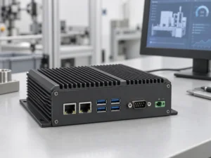
An embedded PC is a computer configured to work as part of a machine or larger …
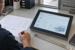
Start with the software the panel PC must run and the conditions it must fit. Then …
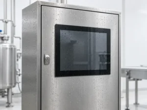
Choosing an industrial panel PC IP rating starts with two questions: what dust and water exposure …
Share your application, requirements, or current challenge. Our team will review the details and recommend a practical way forward.