What Is an Industrial Panel PC? Components, Types and Applications
An industrial panel PC is a computer with a built-in display, usually a touchscreen, designed for …
Eagle Touch Engineering Team
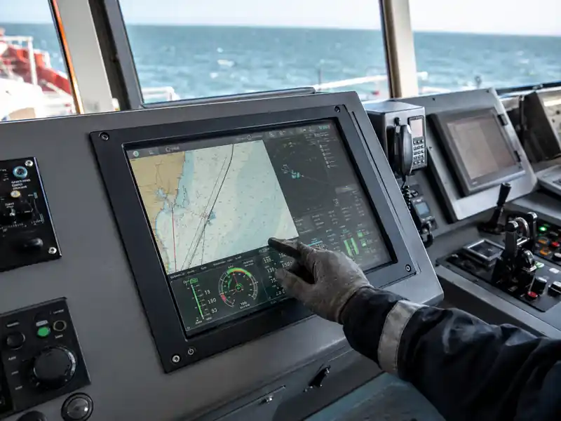
A marine touchscreen monitor must do more than display navigation or equipment data. It must remain readable, responsive and mechanically stable while exposed to glare, moisture, vibration, temperature changes and continuous operation.
These conditions affect almost every part of the display: LCD brightness, front glass, touch technology, optical bonding, sealing, mounting, connectors and power input. A monitor that performs well in an office may become difficult to read, produce false touches or fail prematurely when installed on a vessel.
For equipment manufacturers and system integrators, the correct solution therefore depends on where the monitor is installed and how it will be operated—not simply on screen size or resolution.
Modern vessels combine navigation, engine data, alarms, communication and equipment monitoring into digital control systems. A touchscreen monitor gives operators direct access to these functions without requiring a separate keyboard and mouse at every station.
Typical applications include:
Touch control can reduce panel space and make information easier to access, but it should not automatically replace every physical control. Emergency stops, safety-critical commands and frequently used functions may still require dedicated buttons, switches or another backup input method.
The role of the touchscreen is to provide a clear and efficient operator interface while fitting safely into the overall control architecture.
“Marine use” does not describe one operating environment. A screen inside an enclosed bridge has different requirements from one installed on an exposed deck.
| Installation location | Main display concerns |
|---|---|
| Enclosed bridge | Day and night visibility, low reflection, dimming range, system compatibility |
| Open bridge or deck | Direct sunlight, rain, salt spray, wet touch, stronger sealing |
| Engine room | Heat, vibration, gloves, contamination and continuous operation |
| Offshore equipment | Moisture, corrosion, vibration, outdoor readability and service access |
| Integrated console | Cutout, gasket compression, rear clearance, connectors and thermal design |
Before selecting the display, confirm whether the front surface, rear enclosure or complete monitor will be exposed. This determines whether front-only sealing is sufficient or whether a fully sealed enclosure is needed.
For a broader overview of suitable display platforms, see our industrial displays for marine systems.
Strong sunlight and reflections from water can wash out a standard display. High brightness helps, but brightness alone does not guarantee readability.
The complete optical stack must be considered:
An LCD specified at 1,000 nits will not necessarily deliver 1,000 nits through the finished touchscreen assembly. The touch sensor, glass and coatings all affect the light reaching the operator. Whenever possible, brightness should be confirmed at the front surface of the completed display.
Optical bonding removes the air gap between the touch assembly and LCD. It can reduce internal reflection, improve perceived contrast and lower the risk of condensation at that bonded interface. It does not increase the LCD’s native brightness and does not make the complete monitor waterproof.
Our air bonding vs optical bonding guide explains these differences in more detail.
Night operation also matters. A display that is effective in daylight may still be unsuitable on a bridge if it cannot dim low enough for night use. When day, dusk and night operation are required, the usable dimming range should be evaluated together with maximum brightness.
Projected capacitive touch is widely used in modern marine HMIs because it provides a clear glass surface, accurate response and multi-touch capability. However, standard PCAP settings are not automatically suitable for rain, saltwater or thick gloves.
Water on the surface can change the electrical conditions detected by the touch controller. Depending on the controller, tuning and grounding, this may cause false touches, blocked touch input or reduced accuracy.
A marine PCAP design should therefore be tested with:
Increasing sensitivity for glove operation may also increase sensitivity to water or electrical noise. The correct firmware setting is a balance, not simply the highest available sensitivity.
Resistive touch remains practical where operators use thick gloves or a stylus. It responds to pressure rather than finger capacitance, but normally offers lower optical clarity and more limited multi-touch capability than PCAP.
| Requirement | PCAP touch | Resistive touch |
|---|---|---|
| Bare-finger operation | Excellent | Good |
| Multi-touch gestures | Supported | Normally not required or supported |
| Thick glove operation | Requires validation and tuning | Generally easier |
| Wet surface | Requires controller tuning and testing | Less affected by capacitive water interference |
| Optical clarity | Higher | Lower |
| Hard glass front | Well suited | Construction dependent |
Neither technology is always better. The decision should be based on the operator, gloves, water exposure and software interface.
An IP rating only applies to the structure that was tested. “IP65 front” usually means the installed front face can resist dust and water jets when the gasket is correctly compressed against the customer’s enclosure. It does not mean that the rear housing, connectors or complete monitor are IP65.
For a panel-mounted monitor, sealing depends on more than the glass:
An open-deck monitor may require a complete sealed enclosure and waterproof connectors. A monitor installed inside a protected control cabinet may only require a sealed front surface.
The specification and drawing should clearly state whether the rating covers the front, rear or complete enclosure.
Saltwater does not only affect the display surface. Salt-laden moisture can reach exposed connectors, screws, housing edges and controller boards. Over time, this can cause corrosion, unstable signals or touch-controller failure.
Depending on the exposure level, the design may need:
Optical bonding can remove condensation risk at the bonded LCD interface, but it cannot prevent moisture from entering an inadequately sealed enclosure.
Engines, vessel movement and wave impact create continuous mechanical stress. A display may operate correctly during initial testing but develop intermittent faults if the mounting or cable connections are not stable.
The engineering review should include:
Testing a loose monitor on a bench does not reproduce the mechanical conditions of the completed console. Whenever practical, the sample should be evaluated using the intended mounting structure and cables.
Marine electrical systems may not provide the same stable supply as a laboratory power adapter. Voltage variation, switching loads and electrical noise can affect the display, touch controller and signal connection.
The system integrator should confirm:
A PCAP touchscreen that works correctly with a short USB cable may behave differently after installation near motors, inverters, radios or other noise sources. Grounding and touch tuning should be verified in the production-intent system.
Not every display installed on a boat requires the same certification. Commercial shipping, navigation equipment, offshore systems, recreational vessels and non-navigation control panels may follow different approval paths.
Requirements may include IEC 60945, IACS E10, classification-society approval or specific ECDIS performance standards. These requirements affect component selection, EMC design, environmental testing, documentation, development cost and lead time.
A monitor described as suitable for a marine environment is not automatically a certified marine display. If certification or type approval is mandatory, it should be identified before quotation and sample development—not after the hardware design has been completed.
A production-intent sample should be evaluated under conditions that represent the final vessel installation.
The review should include:
Any claim concerning brightness, IP protection, glove operation, temperature or impact resistance should be connected to a defined test method and the exact product configuration.
To evaluate a custom marine monitor, the supplier should receive:
Eagle Touch develops custom industrial touch monitors with configurable brightness, cover glass, touch technology, optical bonding, interfaces and mounting structures. Our sunlight-readable touch monitor solutions are available for projects where outdoor visibility is a central requirement.
A reliable marine touchscreen monitor is not created by adding a waterproof label to a standard LCD. It is the result of matching the optical stack, touch behaviour, sealing, mechanical structure, electrical design and verification plan to the actual vessel environment.
The most useful starting point is not a long list of preferred specifications. It is a clear description of where the display will be installed, what the operator must do with it and which environmental or certification requirements the completed system must meet.
If you are developing a vessel control system, navigation terminal or offshore equipment interface, send us your installation conditions, drawing and key specifications. The Eagle Touch engineering team can review whether an existing platform, modified monitor or fully custom touch solution is the most practical direction.
An industrial panel PC is a computer with a built-in display, usually a touchscreen, designed for …
An embedded PC is a computer configured to work as part of a machine or larger …
Start with the software the panel PC must run and the conditions it must fit. Then …
Choosing an industrial panel PC IP rating starts with two questions: what dust and water exposure …
Share your application, requirements, or current challenge. Our team will review the details and recommend a practical way forward.