What Is an Industrial Panel PC? Components, Types and Applications
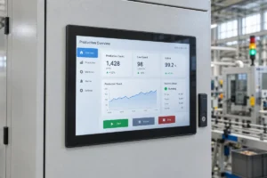
An industrial panel PC is a computer with a built-in display, usually a touchscreen, designed for …
Eagle Touch Engineering Team
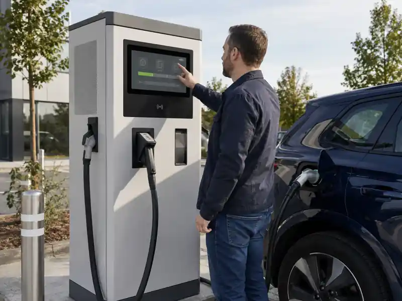
A touch monitor in a DC fast charger is not simply a screen added to the cabinet. It is the point where the driver identifies, starts and follows a charging session. Because the charger is often installed outdoors beside high-power electronics, the monitor must also remain readable, touch-stable and serviceable under conditions that an office display never encounters.
The correct specification therefore depends on two questions: what the user must do on the screen, and what the DC charger will expose the screen to during operation.
A small AC charger may use status lights and a mobile app. A public DC fast charger has a more involved operating sequence. The driver may need to select a connector, choose a language, authenticate, confirm a price, start the session and review charging progress. If charging cannot begin, the equipment must explain what happened and what to do next.
A touch monitor puts these instructions and inputs on one flat interface. The workflow can be updated through software without changing mechanical buttons, while different languages and payment methods can use the same hardware.
The monitor does not normally control the power modules. The charger controller or industrial computer runs the interface and charging software. HDMI, DisplayPort or LVDS carries the image; USB or I²C carries touch input. Payment, networking and OCPP remain functions of the charger system. A panel PC is used only when computing must be integrated with the display.
For a broader look at display architectures used across AC and DC equipment, see our EV charger display design guide.
The screen supports the session from arrival to completion:
A status-only display can be compact, but payment menus, safety messages and live values need enough space to remain legible. Review the UI before fixing the front-panel opening and tooling.
Power modules, contactors and power supplies release heat. The display area can be considerably hotter than the outside air, especially in a sealed metal cabinet under sunlight. A high-brightness backlight adds heat of its own.
Evaluate brightness, operating temperature and cabinet cooling together, and keep the display away from the main hot-air path where possible. Check operating temperature, not the usually wider storage-temperature rating.
Public chargers face sun, vehicle reflections, rain, condensation, dust and winter gloves. High brightness alone does not guarantee readability. Cover-glass reflection, viewing angle, surface treatment and the optical air gap also matter. Many outdoor projects begin around 1,000 nits, but the target must be confirmed on the assembled charger.
Optical bonding can reduce internal reflections between the LCD and touch glass. AG or AR treatment may also help, although each affects the surface differently. Our sunlight-readable monitor guide explains why brightness cannot be selected alone.
A standard PCAP controller may interpret water as input or stop responding under a water film. Glove mode needs greater sensitivity, while water rejection must suppress unwanted signals. Tune both with the final glass, grounding and metal enclosure—not only on an open bench.
Poor grounding, an unstable DC supply or unshielded cables can cause false touches, intermittent USB connection, flicker or resets when the charger starts.
Test the touch controller, display board and cable arrangement while the power modules operate. Shielding, secure connectors, grounding and separation from high-current wiring can be as important as the monitor specification.
The front may be struck, scratched or cleaned repeatedly. Strengthened glass and solid support help, but glass thickness alone does not prove an impact rating. If IK10 is required, evaluate the complete mounted assembly. See our IK10 touch screen page.
A failed display can make an otherwise functional charger unusable. It should be replaceable without disturbing the high-power section, with the LCD, touch controller, connectors and mechanical version controlled during repeat production.
The following is a practical starting point, not a universal DC charger specification.
| Item | Typical project direction | What must be confirmed |
|---|---|---|
| Screen size | 10.1″, 15″ or 15.6″ | UI content, viewing distance, installation height and cabinet opening |
| Brightness | Around 1,000 nits or higher for many outdoor projects | Direct sun, glass reflection, bonding, installation angle and thermal limit |
| Resolution | 1280 × 800, 1024 × 768 or 1920 × 1080 | Controller output and native UI aspect ratio |
| Touch | Industrial PCAP | Required glove type, rain behaviour, glass thickness and grounding |
| Optical stack | AG or AR glass; optical bonding where needed | Readability target, surface durability and cost |
| Protection | Front IP65 is commonly requested | Gasket compression, cabinet cut-out and whether full-enclosure protection is required |
| Impact resistance | Strengthened 3–6 mm cover glass, project dependent | Required IK level and complete mounted-assembly test |
| Temperature | Wide-temperature components, often −20°C to +70°C | Actual internal temperature at full charging load |
| Interfaces | HDMI/DP plus USB, or LVDS plus I²C | Host board, cable length, connector locking and service access |
| Power | 12V or 24V DC | Voltage variation, start-up behaviour, grounding and surge requirements |
| Mounting | Open-frame, panel-mount or custom structure | Front appearance, sealing surface, depth and replacement direction |
Standard and customized configurations can be reviewed on our outdoor touch monitor product page.
Common integration failures include:
These are not always component defects. A bench test cannot reproduce every thermal, optical and electrical condition inside the finished charger.
Install the engineering sample in the actual cabinet and confirm:
Agree any certification level and responsible assembly before sampling. A component certificate does not automatically cover the complete charger.
A useful RFQ includes screen size, native resolution, sunlight exposure, operating temperature, touch conditions, cover-glass drawing, impact requirement, mounting, interfaces, power input, cable direction and annual quantity. Front-panel and internal-layout drawings help check fit, sealing and heat exposure.
Eagle Touch supplies custom touch monitor solutions for OEM charging equipment, including high-brightness LCDs, PCAP tuning, optical bonding, custom glass, front sealing and open-frame or panel-mount structures.
The correct DC fast charger touch monitor is not defined by one headline specification. It is the display assembly that remains clear, responsive and replaceable after it is installed beside the charger’s power electronics and exposed to real users, weather and operating heat.
An industrial panel PC is a computer with a built-in display, usually a touchscreen, designed for …
An embedded PC is a computer configured to work as part of a machine or larger …
Start with the software the panel PC must run and the conditions it must fit. Then …
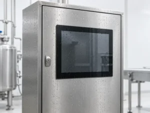
Choosing an industrial panel PC IP rating starts with two questions: what dust and water exposure …
Share your application, requirements, or current challenge. Our team will review the details and recommend a practical way forward.