What Is an Industrial Panel PC? Components, Types and Applications
An industrial panel PC is a computer with a built-in display, usually a touchscreen, designed for …
Eagle Touch Engineering Team
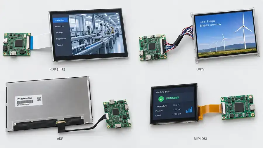
An LCD can have the right size, brightness and resolution and still be incompatible with your mainboard. Even a matching connector does not guarantee that the display will work.
Start with the board’s available display output and the LCD’s exact input requirements. Then check timing, electrical compatibility, cable routing and software support. RGB, LVDS, eDP and MIPI DSI can all work in industrial equipment when the board, panel and connection are properly matched.
This article covers internal connections between a mainboard or display controller and an LCD module. For external computer-to-monitor connections, see our HDMI, DisplayPort and USB-C guide.
| Interface | How it carries display data | Main selection consideration |
|---|---|---|
| Parallel RGB, often called TTL | Streams pixel data across parallel signal lines | Host timing support and routing of multiple signals |
| LVDS | Sends serialized pixel data over differential pairs | Channel configuration, colour depth and data mapping |
| eDP | Uses a packet-based embedded display link | Compatible lane count, link rate and platform support |
| MIPI DSI | Sends display data through a serial interface | Host compatibility, operating mode and panel initialization |
| SPI | Writes commands and pixel data to a display controller | Transfer speed for the intended screen updates |
| MCU parallel, such as 8080 | Writes commands and pixel data over a parallel bus | Bus timing, controller commands and available host pins |
These interfaces do not have universal connector shapes, cable lengths or screen-size limits. Always check the specifications of the actual board and LCD.
If the mainboard is already selected, check which display outputs are available at its connectors. A processor may support an interface that the board does not expose. Ask the board supplier which panel configurations its hardware and firmware support.
If the LCD is already selected, provide its full part number and datasheet. A description such as “10.1-inch LVDS screen” is insufficient to select a compatible controller or cable.
If both are still open, evaluate them together. Include the harness, software work and replacement options when comparing costs. A cheaper LCD may require an additional bridge board or more development time.
When the interfaces differ, an active conversion solution may be possible. For example, a DSI-to-eDP bridge converts the video protocol within defined operating limits. Changing the cable alone cannot perform this conversion. Confirm the direction, supported display modes, power requirements and configuration work before committing to the design.
Parallel RGB is worth considering when the host has a compatible LCD controller. Pixel data travels alongside a pixel clock and the synchronization or data-enable signals required by the panel.
The main trade-off is the number of signal lines. Routing becomes more demanding as the pixel clock increases, and the host must deliver display data consistently.
Check the specified I/O voltage; the catalogue term “TTL” does not establish voltage compatibility. The panel’s timing requirements must also match the host configuration. STMicroelectronics’ LCD controller documentation provides examples of parallel RGB signals and timing.
RGB can be a straightforward choice for a supported embedded design. It should not be selected on the assumption that any RGB panel will work with any RGB output.
LVDS is a practical option when the board supplier already supports a suitable LCD and harness. Keeping an approved combination can reduce integration work when updating an existing machine.
The important detail is how pixel data is arranged. Check single- or dual-channel operation, colour depth and the mapping specified by both devices. Terms such as JEIDA and VESA are commonly used to distinguish mappings, but the actual datasheets remain the reference.
A mapping mismatch can cause incorrect colours even when the display produces an image. TI’s LCD data-mapping note explains these interoperability issues.
Differential signalling does not make every harness suitable. Cable construction, routing and the operating signal rate still need to be validated.
Consider eDP when the mainboard provides a supported eDP output and a suitable panel is available. It can accommodate higher-bandwidth designs, but it is not restricted to high-resolution displays.
The host and panel need compatible lane counts and link rates. Panel power, the AUX communication path, link training and firmware configuration also matter.
Ask the board supplier whether the proposed LCD has been tested, or what configuration is needed to support it. A connector labelled “eDP” is only the starting point.
An eDP panel can be replaced with an approved compatible model. Replacement flexibility depends on the selected hardware and configuration, rather than the interface name alone.
MIPI DSI deserves consideration when the processor platform provides a suitable DSI host. Confirm the physical interface, lane configuration, pixel format and operating mode.
Be precise about the interface name. A MIPI CSI camera connector is not a substitute for a MIPI DSI display connection.
Software support should be checked early. Request the panel initialization sequence, reset requirements and available driver information before ordering samples. Two displays with similar electrical connections may require different initialization commands.
MIPI DSI includes video and command operating modes. The host and panel must support the intended mode; a working example for another screen does not establish compatibility with your selected LCD.
SPI and MCU parallel interfaces send commands and pixel data to a display controller, typically with display memory. They are different interfaces, but both can be useful for embedded control screens.
SPI uses relatively few signal lines. Its transfer speed can become a constraint when large areas of the screen need frequent updates. A static status screen and a smoothly scrolling interface place very different demands on the same connection.
MCU parallel interfaces use more signals and can provide greater throughput, depending on the bus and controller. Check the command set and timing requirements as well as the bus width.
Evaluate the actual menus, animations and update frequency. A sample displaying a still image does not demonstrate the performance of the finished user interface. ST’s SPI display guidance illustrates the role of display-memory updates and synchronization.
Review the LCD datasheet and mainboard documentation together. The interface comparison helps narrow the options; the following checks determine whether the selected parts can work together.
| Check | What to confirm |
|---|---|
| LCD identification | Full model number and specification revision |
| Connector and pin assignment | Connector model, contact orientation, power pins and signal positions |
| Electrical requirements | Panel supply, logic levels and required power capacity |
| Display timing | Resolution, refresh rate, pixel clock and applicable blanking and polarity requirements |
| Interface configuration | The interface-specific settings described above |
| Firmware and software | Required BIOS settings, panel driver, initialization commands or controller configuration |
| Power sequence | Required order and delays for power, reset, display signals and backlight control |
A matching pin count does not prove that power and signal positions match. Likewise, two panels with the same resolution may require different timing or configuration.
For a replacement LCD, repeat this review before treating it as interchangeable. Do not rely on appearance, diagonal size or a similar part number.
Backlight drive and touch communication also need separate checks. A correct video connection does not establish compatibility with the LED backlight or touch controller. See our LCD backlight selection guide for backlight requirements.
Use the intended production harness, connector retention and cable route during sample testing. A short bench cable does not validate a longer harness installed beside switching power electronics.
Test cold starts, restarts, power recovery and sleep/wake where applicable. Run the target display mode with colour patterns, text and moving content. Look for incorrect colours, flicker, intermittent image loss and failures that appear only after repeated starts.
Check operation across the project’s required temperature range and during the relevant EMC evaluation. There is no single safe cable length for every LCD using the same interface; the transmitter, receiver, signal rate and interconnect design all affect the result.
Record the approved LCD revision, board firmware and cable drawing. When one changes, review and repeat the affected checks before production.
For an Eagle Touch project review, send the LCD datasheet, mainboard model, target resolution and refresh rate, cable length, operating system and expected quantity. Contact our team to discuss the display connection before sampling.
An industrial panel PC is a computer with a built-in display, usually a touchscreen, designed for …
An embedded PC is a computer configured to work as part of a machine or larger …
Start with the software the panel PC must run and the conditions it must fit. Then …
Choosing an industrial panel PC IP rating starts with two questions: what dust and water exposure …
Share your application, requirements, or current challenge. Our team will review the details and recommend a practical way forward.