What Is an Industrial Panel PC? Components, Types and Applications
An industrial panel PC is a computer with a built-in display, usually a touchscreen, designed for …
Eagle Touch Engineering Team
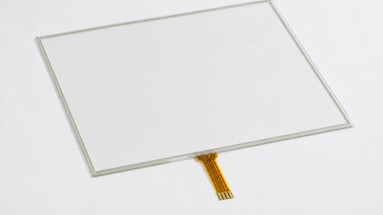
Resistive touchscreens are no longer the default for consumer electronics, but that does not make them obsolete. They remain a sensible choice when an operator must use a thick glove, a passive stylus or another non-conductive object to control equipment.
The technology also has clear limitations. A conventional resistive screen normally supports single-point input, its flexible PET surface is easier to scratch than cover glass, and its optical performance is usually lower than that of a typical PCAP assembly.
The right question is therefore not whether resistive touch is old or new. It is whether pressure-based input, the mechanical structure and the expected duty cycle fit the equipment.
A resistive touchscreen is a pressure-sensitive touch sensor. It uses two transparent conductive surfaces separated by a very small gap. When the upper surface is pressed, the two conductive coatings contact each other. A controller measures the resulting voltage and converts it into X and Y coordinates.
Because activation depends on pressure rather than the electrical conductivity of the touching object, the screen can be operated with a bare finger, a gloved hand or a passive plastic stylus.
That operating principle explains both its value and its limits: it accepts almost any pointing object, but the upper surface must remain flexible and is therefore a mechanical wear component.
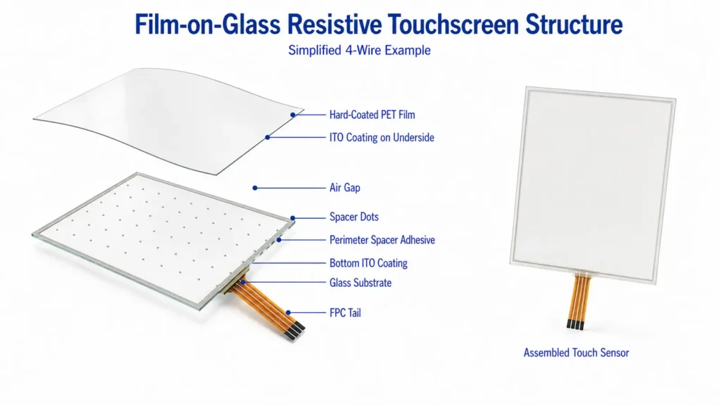
A common film-on-glass, or F+G, resistive sensor contains:
When pressure is applied, the PET film bends locally until the two ITO-coated surfaces meet. The controller establishes a voltage gradient, reads the voltage at the contact point and calculates the touch position.
The controller is part of the system, not an optional cable adapter. A raw resistive sensor normally produces an analog signal and does not connect directly to USB. USB or RS-232 is usually the output of a separate controller board.
| Characteristic | What It Means in Real Equipment |
|---|---|
| Activation method | Requires physical pressure; the touching object does not need to be conductive |
| Input objects | Works with a finger, thick glove or passive stylus when sufficient pressure is applied |
| Touch mode | Conventional 4-wire and 5-wire sensors are normally single-touch |
| Interface style | Well suited to buttons, menus, numeric entry and precise point selection; not intended for pinch or multi-finger gestures |
| Surface | Uses a flexible PET operating surface that is more vulnerable to scratches and wear than cover glass |
| Optical performance | The film, conductive coatings and internal interfaces reduce transmission and add reflection compared with a typical PCAP assembly |
| Water on the surface | Droplets do not normally create a touch unless they apply sufficient pressure; this does not make the assembly waterproof |
| Controller | Requires the correct wire configuration, pinout, controller and calibration |
| Service life | Depends on the sensor construction, activation force, touch location and supplier specification; the top film remains a wear component |
| Project cost | Must be quoted for the actual size, construction, controller, customization, quantity and supply requirements |
Two points are often misunderstood. First, “works when wet” is not the same as waterproof. Water can still enter around the bezel, sensor edge, FPC exit or LCD assembly. Second, resistive touch is not automatically cheaper than PCAP. The finished project cost depends on the complete assembly, not the sensing principle alone.
A rigid cover lens also cannot normally be placed over the active surface of a conventional resistive touchscreen because the PET film must flex. If impact-resistant glass, multi-touch or a flush glass operating surface is mandatory, evaluate PCAP or a purpose-designed rugged resistive construction. For a complete technology comparison, see PCAP vs Resistive Touch Screen for Industrial Equipment.
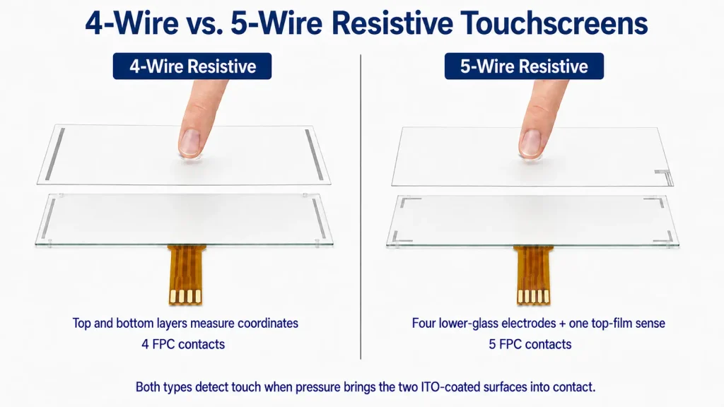
Four-wire and five-wire sensors both detect contact between two conductive surfaces, but they generate and measure the coordinate signal differently.
| Item | 4-Wire Resistive | 5-Wire Resistive |
| Coordinate generation | The two conductive layers alternate between X- and Y-axis measurement | Both X- and Y-axis voltage gradients are generated on the lower glass |
| Role of top film | Participates in coordinate measurement | Acts mainly as a voltage-sensing probe |
| Effect of top-film electrical wear | Can affect linearity and calibration | Less likely to cause the same coordinate drift |
| Typical use | Moderate-duty controls and compatible replacement projects | Frequent-use controls where long-term coordinate stability matters |
| Controller | Requires a 4-wire controller | Requires a 5-wire controller |
In a 4-wire sensor, one conductive layer establishes the voltage gradient for one axis and the other layer establishes it for the second axis. The controller switches the electrical roles of the two layers to obtain both coordinates.
Because both layers participate in measurement, changes in the electrical uniformity of the flexible top layer can eventually affect linearity or calibration. A 4-wire screen can still be the correct choice when the expected touch frequency is moderate, the required service specification is available and the existing controller is compatible.
In a 5-wire sensor, four connections around the lower glass create the voltage gradients for both axes. The fifth connection is attached to the upper conductive film, which acts mainly as the sensing probe.
This makes coordinate performance less dependent on the electrical uniformity of the top film. The surface can still be scratched or punctured, but ordinary conductive wear on the upper layer is less likely to produce the same coordinate drift seen in a conventional 4-wire design.
Five-wire is therefore often preferred for frequently operated fixed controls. It is not automatically better for every project: controller compatibility, availability, dimensions and the qualified sensor specification still decide the choice.
Eight-wire resistive sensors also exist. They use a principle similar to 4-wire touch but add sensing connections to compensate for voltage loss at the panel edges. They are mainly relevant to specialized or legacy systems; confirm controller support and long-term availability before specifying them.
The diagonal size is not enough to specify a resistive touchscreen. The following items should be confirmed on a controlled drawing and product specification.
| Specification | Why It Matters |
| Construction | Confirms F+G or another approved stack and the actual total thickness |
| Wire configuration | Must match the controller and replacement system |
| Overall, active and viewing areas | Determines alignment with the LCD, bezel and displayed interface |
| Activation force | Affects operating feel and performance with gloves or a stylus |
| Linearity and accuracy | Define coordinate performance before and after calibration |
| Light transmission and haze | Affect display brightness, contrast and clarity |
| Surface hardness | Indicates resistance to scratching but does not define total service life |
| Activation-life rating | Must be evaluated against actual touches per day and repeated use of fixed controls |
| Operating and storage temperature | Must match the complete equipment environment, not only the LCD rating |
| FPC details | Include position, direction, length, pitch, contact side and pin definition |
| Insulation and edge-seal areas | Determine where the bezel or gasket may safely contact the sensor |
| Controller and host interface | Confirm 4/5/8-wire support, calibration, drivers and USB, serial or other host output |
Avoid copying a “typical” value from another supplier’s catalogue. Activation force, transmission, resistance, hardness and touch-life ratings vary with the panel construction and test method. The approved specification for the selected part is the only useful production reference.
A sensor can have the correct nominal size and still be impossible to install. Confirm the outline, active area, viewing area, thickness, FPC exit, connector orientation and available bending space. For a replacement project, the original sensor drawing is more useful than the cabinet opening alone.
The bezel or gasket must not continuously preload the active or sensitive area. Uneven compression can create false touches, dead zones or unstable coordinates. Place the gasket on the approved border and control its hardness, thickness, compression, enclosure flatness and screw torque.
Match the controller to the wire configuration and pinout. Keep analog connections short and well routed, then verify grounding, filtering and calibration in the finished enclosure. Electrical noise, long cables and power-supply variation can reduce coordinate stability even when the sensor itself is within specification.
Specify actual operating temperature, humidity, sunlight exposure, contaminants, cleaning chemicals, glove type and touches per day. “Industrial grade” is not an acceptance criterion. For outdoor or frequently cleaned equipment, pay particular attention to PET aging, surface abrasion, edge sealing and enclosure ingress protection.
Many resistive sensors are attached to the LCD with perimeter adhesive, leaving an air gap between the sensor and display. Optical bonding can reduce internal reflection and parallax, but it does not make the exposed PET surface scratch-resistant. The bonding material and process must be validated for the selected sensor. See Optical Bonding vs Air Bonding for the separate bonding decision.
Choose resistive touch when the equipment has a clear requirement for pressure input, a passive stylus, thick-glove operation, legacy controller compatibility or a simple single-point interface.
Do not choose it merely because it is assumed to be cheaper or more “industrial.” A modern PCAP system is usually the better direction when the product needs multi-touch, a durable glass operating surface, high optical clarity or a flush consumer-style appearance.
For an existing industrial platform, compatibility may matter more than theoretical performance. Keeping a proven wire configuration, controller and mechanical design can be lower risk than changing the complete input system. For a new platform, select the touch technology according to how operators will actually use the equipment over its full service life.
It does not require a conductive glove, but the glove must transmit enough pressure to deflect the top film. Very soft or bulky gloves should be tested on the finished assembly rather than approved from a general claim.
Not necessarily. Accuracy depends on the sensor, controller, calibration, mounting and electrical environment. The main 5-wire advantage is that long-term coordinate performance is less dependent on the electrical condition of the flexible top layer.
Not as a direct electrical replacement. The controller and pinout are different. The change may also affect the FPC, connector, calibration and mechanical drawing.
A good resistive touchscreen project starts with the operator, not the catalogue. Confirm what will touch the screen, how often it will be used, what surface damage is likely and whether the existing controller must be retained. Then lock the controlled drawing, electrical interface and acceptance criteria before production.
For a custom or replacement project, provide the LCD model, touchscreen drawing, FPC details, controller model, operating environment and expected quantity. Eagle Touch can evaluate a standalone custom resistive touchscreen, a bonded LCD assembly or a complete industrial display solution.
An industrial panel PC is a computer with a built-in display, usually a touchscreen, designed for …
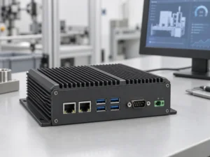
An embedded PC is a computer configured to work as part of a machine or larger …
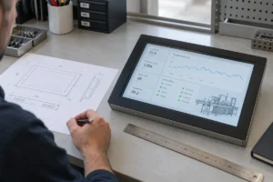
Start with the software the panel PC must run and the conditions it must fit. Then …
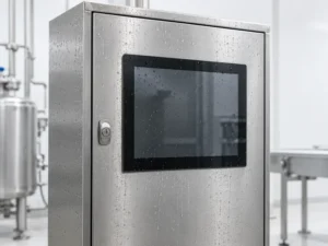
Choosing an industrial panel PC IP rating starts with two questions: what dust and water exposure …
Share your application, requirements, or current challenge. Our team will review the details and recommend a practical way forward.