What Is an Industrial Panel PC? Components, Types and Applications
An industrial panel PC is a computer with a built-in display, usually a touchscreen, designed for …
Eagle Touch Engineering Team
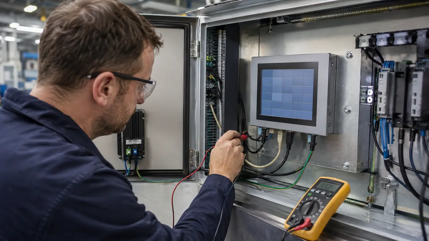
An LCD touchscreen can show a perfect image while the touch function is completely dead. It can also continue sending touch data while the screen is black. A display may work on the bench, then fail after it is installed beside a motor, inside a sealed cabinet, or behind a tightly compressed gasket.
These are not contradictions. An industrial touchscreen display contains several systems that work together but can fail separately: input power, video source, controller, LCD panel, backlight, touch sensor, touch controller, cover glass, bonding layer, cables, and enclosure.
That leads to one practical rule:
The display is often where the failure becomes visible, not where the failure starts.
This guide helps you identify the symptom, locate the most likely fault area, and choose the first useful test. It does not assume that every screen problem requires a new LCD or touch panel.
| What You See | Likely Area to Check First | First Isolation Test |
|---|---|---|
| Screen is completely black | Input power, source, controller, backlight | Check the power indicator and OSD menu |
| Image flickers or disappears briefly | Power, video cable, timing, backlight control | Check whether the OSD also flickers |
| Screen is dim but an image remains visible | Brightness setting, dimming, LED driver, backlight | Check brightness control and look for a faint image |
| Vertical or horizontal lines appear | Source, cable, controller, LVDS/eDP connection, LCD | Test with a known-good source and cable |
| Fixed bright, dark, or colored points remain | LCD pixel, contamination, local pressure | Display solid white, black, red, green, and blue patterns |
| A previous image remains after the content changes | TFT LCD image retention | Show moving content and observe whether it fades |
| Image is normal but touch is dead | Touch cable, controller, host, firmware | Check whether the host detects the touch controller |
| Touch points appear without contact | Water, EMI, grounding, power noise, tuning | Compare bench operation with the final installation |
| Touch position is offset or drifting | Mapping, rotation, scaling, pressure, firmware | Confirm display resolution, orientation, and touch mapping |
| One area does not respond to touch | Sensor electrode, FPC, controller channel, local pressure | Run a full-screen line or grid test |
| Touch changes with gloves or water | Sensitivity, glass stack-up, controller tuning | Test the final assembly with the actual glove or wet condition |
| Bubbles, cracks, or pressure marks appear | Bonding, cover glass, support, mounting pressure | Record the location and inspect the surrounding structure |
Do not change several conditions at once. A useful diagnosis changes one item, repeats the same test, and records whether the symptom follows the display or remains with the machine.
The same screen can behave differently after installation because the machine changes its electrical, mechanical, and thermal environment.
| Test Result | More Likely Direction |
| The fault follows the same display when moved to another known-good system | Display, controller, cable, backlight, or touch module |
| The fault remains with the machine after the display is changed | Power, source, grounding, wiring, enclosure, software, or environment |
| The display works on the bench but fails after installation | Grounding, EMI, cable routing, bezel pressure, heat, or enclosure integration |
| Several units fail under the same operating condition | Repeated system, installation, environmental, or configuration issue |
| One unit fails under every test condition | Individual component or assembly failure is more likely |
| The result changes when one cable, supply, or source is replaced | The changed item or its compatibility is part of the fault path |
The point is not to protect the display supplier or blame the machine builder. The point is to find the condition that reproduces the fault.
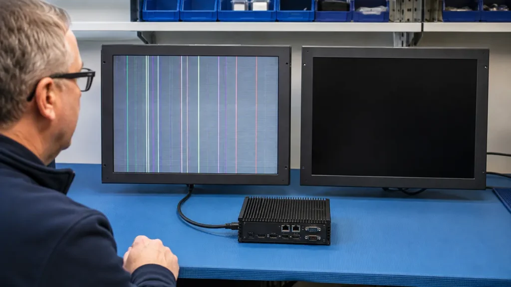
A black screen does not identify the failed component. The monitor may have no input power, the backlight may be off, the controller may not be receiving a supported signal, or the host may have stopped producing an image.
Start with observations that do not require disassembly. Is the power indicator on? Does the OSD menu appear? Is the screen faintly illuminated? Does touch still respond? If the OSD appears, the local display path is working at least partially, so the source, selected input, cable, and video timing deserve attention before the LCD is replaced.
If the screen remains black, use the dedicated industrial display black-screen troubleshooting guide to isolate power, signal, controller, and backlight faults in the correct order.
Flickering may look like changing brightness, a shaking image, moving noise, or a picture that disappears and returns. Those symptoms do not always have the same cause.
Open the OSD menu or disconnect the video input and observe the no-signal screen. If the OSD remains stable while the source image flickers, concentrate on the host, video cable, adapter, resolution, and refresh timing. If the OSD also flickers, check the monitor input power, backlight control, and internal electronics.
Record whether the fault begins during startup, after warm-up, or when a motor, relay, heater, or inverter operates. The complete test sequence is covered in Industrial Monitor Flickering: Diagnose the Fault Before Replacing the Display.
Gradual brightness loss and a sudden brightness drop should not be diagnosed in the same way.
LED backlights normally lose output gradually with operating time, and heat can accelerate that process. A sudden reduction is more likely to involve the brightness setting, automatic dimming, PWM control, thermal derating, input power, LED driver, or a loose backlight connection.
First confirm the commanded brightness and whether a light sensor or external dimming input is active. If a very faint image is visible while the screen appears dark, the LCD may still be forming an image and the backlight path should be checked. For outdoor equipment, compare the brightness and enclosure temperature under shade and real solar exposure rather than judging the display only indoors.
Lines and corrupted images can originate before the signal reaches the LCD. A damaged external video cable, unsupported timing, controller fault, loose internal LVDS/eDP connection, or source problem can produce symptoms that resemble panel failure. Fixed lines that remain with the same display under every source and cable test point more strongly toward the internal signal path, COF connection, or LCD panel.
Start with a short, known-good video cable and a confirmed working source. Use the monitor’s supported input timing and native panel resolution where possible. For an embedded display, power down before inspecting or reseating internal connectors. Do not connect or disconnect LVDS or eDP cables while energized unless the hardware documentation explicitly allows it.
These defects are often grouped together, but they are not identical.
Display solid white, black, red, green, and blue test patterns and photograph the result from the same position. Do not press the panel to test the defect. Compare true pixel defects with the LCD acceptance specification agreed for the project. If a mark appears only after assembly or near a screw, gasket, or frame edge, inspect the mounting structure before rejecting the LCD.
Image retention is a faint previous image that remains visible after the content changes. It is often associated with a static HMI page, logo, QR code, status bar, or button area displayed for long periods. On a TFT LCD, temporary image retention is not automatically the same as permanent OLED burn-in.
Change to moving content or alternating test patterns and record whether the retained image fades. Also note the operating time, brightness, enclosure temperature, and repeated UI pattern. The full validation and prevention method is explained in our guide to TFT LCD image retention in industrial touch monitors.
Yellowing or general color shift follows a different path. Check the source settings first, then inspect whether discoloration is localized near an edge, heat source, adhesive area, or region exposed to sunlight or cleaning chemicals.
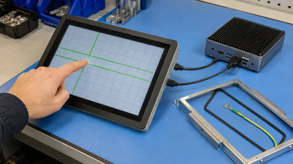
If the image is normal but there is no touch input, the display signal path has already proved very little about the touch path. HDMI, DisplayPort, VGA, DVI, LVDS, or eDP may carry the image while touch data uses USB, I²C, UART, RS232, or an internal FPC connection.
The first useful question is whether the operating system or host detects the touch controller. If it does not, test a known-good touch cable, port, and power condition before removing the sensor. If the controller is detected but no points are reported, continue with firmware, mapping, FPC, controller, and sensor checks.
Follow the dedicated industrial touch screen not responding checklist for the complete isolation order.
Ghost touch means that the controller reports one or more touch points when nobody is touching the screen. In an industrial HMI, charger, kiosk, or payment terminal, that is more than a nuisance because it can trigger an unintended command.
The timing of the failure is the best starting evidence. Does it occur after rain or cleaning? Only when the cabinet door is closed? When a charger, motor, or inverter starts? Only with the final power supply or cable length?
Compare the touch panel outside the equipment with the same panel inside the final enclosure. If the fault follows the machine condition rather than the panel, use the touch screen interference guide to investigate grounding, power noise, shielding, and cable routing. For a broader symptom comparison, see common industrial capacitive touchscreen problems.
Touch offset means the reported coordinate does not match the point touched. A fixed and repeatable offset often indicates display rotation, resolution, scaling, multi-monitor mapping, calibration, or firmware configuration. A result that changes after installation may involve mechanical pressure, sensor alignment, FPC stress, or grounding.
Confirm that the display orientation and touch orientation match. Check the active display, native resolution, operating-system scaling, and touch mapping before recalibrating. If accuracy returns when the display is removed from the enclosure or the bezel pressure is released, the structure—not calibration—is the more useful place to investigate.
See Why Industrial Touch Screens Lose Accuracy in Harsh Environments for the detailed accuracy and integration checks.
A dead zone is a repeatable area that does not report touch while the rest of the active area works. It may be related to a sensor electrode, controller channel, damaged FPC, unsuitable firmware, or local mechanical pressure. Dirt or an overlay can also obstruct some touch technologies, but it should not be assumed to explain a fixed electrical dead zone.
Remove the display from the enclosure where practical and draw slow horizontal and vertical lines across the complete active area using a diagnostic grid. Repeat the test with the same controller and cable. A dead region that remains in exactly the same position is more likely to follow the touch assembly; a region that changes after mounting pressure is released points toward mechanical integration.
“Supports gloves” and “works when wet” are not complete specifications. Glove material and thickness matter. Water droplets, a thin film, flowing water, wet fingers, and operation under continuous rain are different conditions for a capacitive controller.
Test the final cover glass thickness, bonding method, sensor, controller firmware, enclosure, and actual glove together. Increasing sensitivity without checking the full system can improve glove response while making the screen more vulnerable to water or electrical noise.
The correct goal is not maximum sensitivity. It is enough signal margin for the intended user while maintaining stable rejection of unintended input. Use the industrial touch screen sensitivity adjustment guide when the problem changes with glass thickness, gloves, water, or the final stack-up.
The location and shape of a physical defect often reveal more than its name.
| What You See | Direction to Investigate |
| Bubble between LCD and touch assembly | Bonding material, process, curing, contamination, heat, or humidity exposure |
| Delamination beginning at an edge | Edge adhesion, sealing, material compatibility, or structural movement |
| Crack beginning from a glass edge | Edge impact, insufficient support, handling, or enclosure stress |
| Crack or pressure mark near a screw | Uneven fastening force, gasket compression, or chassis distortion |
| Surface scratches or coating damage | Abrasion, wiping material, or cleaning-chemical compatibility |
Optical bonding and air bonding should be reviewed according to the actual display stack and working environment. Optical bonding can eliminate the air gap between layers and reduce internal reflection, but it does not make the complete monitor waterproof. Edge sealing, gasket design, cable exits, drainage, and enclosure protection remain separate requirements.
For a new design, review the industrial touch screen cover glass together with support, edge protection, impact requirement, thickness, strengthening method, printing, bonding, and touch tuning. If the damage followed repeated cleaning, compare the process with the safe touch screen cleaning guide.
When the cause is still unclear, use the same order every time:
Power down before reseating internal cables. Live-voltage, ripple, waveform, or internal power measurements should be performed only by qualified personnel using the correct product documentation and equipment.
A message that says “the screen is bad” is difficult to act on. Useful evidence includes:
This information helps separate an individual display defect from a repeated integration condition before more parts are replaced.
Eagle Touch supports industrial touchscreen displays, monitors, and Panel PCs for OEM equipment. If a display works during sample testing but fails after installation—or if the same fault is repeating across several units—send us the symptom evidence and final machine conditions.
We can review the LCD, controller, touch system, power input, grounding, cables, bonding, cover glass, mounting structure, and operating environment as one system before recommending repair, replacement, or redesign.
Send your project and fault information to Eagle Touch.
Common problems include black screens, flickering, dim backlights, vertical or horizontal lines, pixel defects, image retention, no touch response, ghost touch, coordinate offset, touch dead zones, unstable glove or wet-touch performance, and bonding or cover-glass damage.
Installation changes the electrical, mechanical, and thermal environment. Grounding, EMI, cable routing, enclosure pressure, heat, moisture, power quality, and the final glass stack can affect a display that worked normally in an open bench test.
Check whether the OSD appears and whether a faint image remains visible when the screen looks dark. A faint formed image suggests that the LCD signal path may still be operating while the backlight, LED driver, enable, dimming, or backlight power path requires investigation.
Ghost touch may be created by water, grounding, power noise, EMI, cable routing, enclosure contact, controller tuning, or the final glass structure. If the fault remains with the same machine condition after the panel is changed, replacing more panels will not remove that condition.
Yes. Component testing confirms basic operation, but the final machine introduces the real power supply, cable length, grounding, enclosure pressure, heat, moisture, vibration, nearby electrical loads, and user conditions. Those factors should be included before mass production approval.
An industrial panel PC is a computer with a built-in display, usually a touchscreen, designed for …
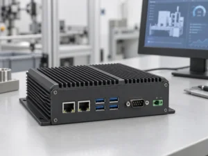
An embedded PC is a computer configured to work as part of a machine or larger …
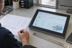
Start with the software the panel PC must run and the conditions it must fit. Then …
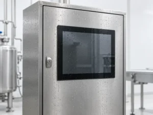
Choosing an industrial panel PC IP rating starts with two questions: what dust and water exposure …
Share your application, requirements, or current challenge. Our team will review the details and recommend a practical way forward.