What Is an Industrial Panel PC? Components, Types and Applications
An industrial panel PC is a computer with a built-in display, usually a touchscreen, designed for …
Eagle Touch Engineering Team
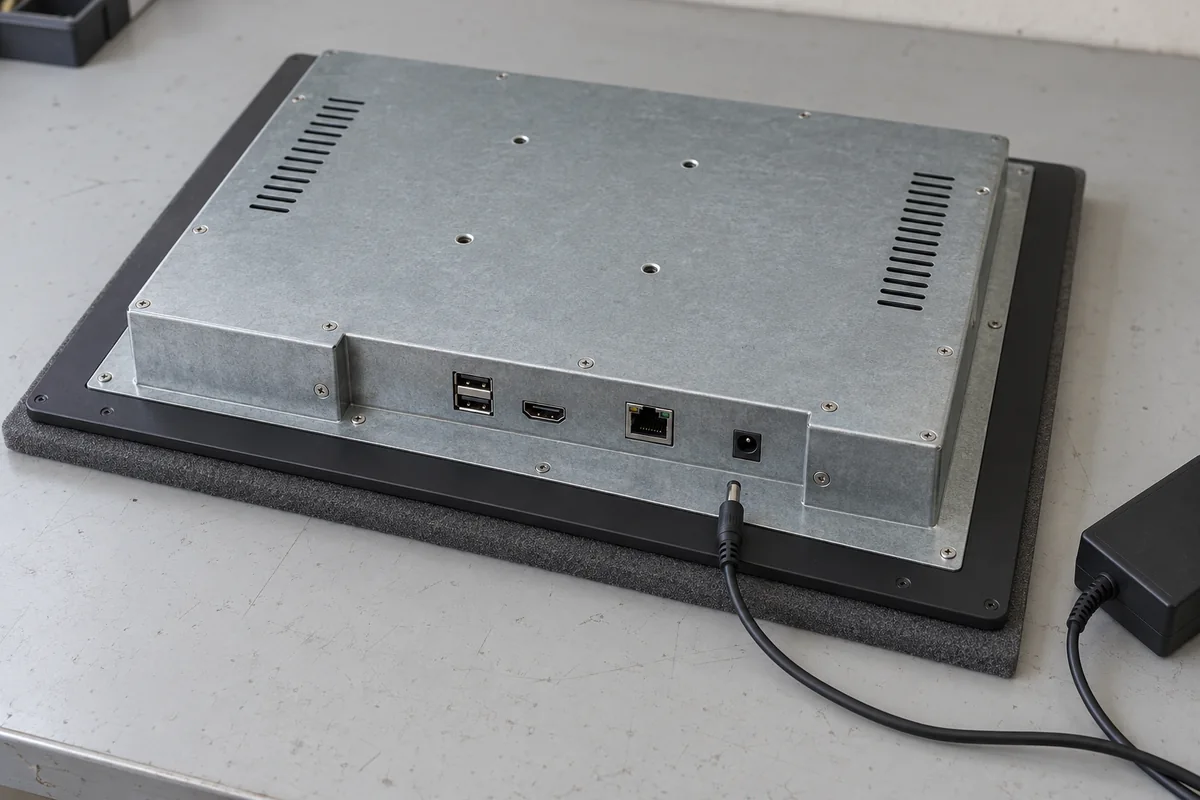
If an industrial panel PC is not powering on, start with its power supply, connections and switch-on method. A dark screen alone does not prove that the computer has no power. Establish what the unit is doing before opening the housing or ordering a replacement.
The checks below focus on equipment with no apparent startup response. Use the manual and electrical ratings for the exact model, including any custom configuration.
Record the symptoms before disconnecting anything. A short video of the startup attempt can be more useful than a description of a “dead screen.”
| What you observe | Where to start |
|---|---|
| No indicator and no apparent startup response | Check input power, connections and the required switch-on method. |
| An indicator lights, but the screen stays dark | Check the indicator meaning and whether the computer is actually running. Power to an indicator does not confirm successful startup. |
| A logo, BIOS screen or boot error appears | The unit has powered on. Investigate the boot process rather than treating it as a complete power failure. |
| The unit starts briefly, switches off or repeatedly attempts to start | Check input voltage during the event, connected loads and model-specific fault indications. |
Indicator meanings vary by model. Fan movement is also an unreliable test on its own: some panel PCs are fanless, and others control fan speed by temperature.
If the computer is running but the screen remains blank, follow our industrial display black-screen troubleshooting guide for the display-side checks.
Before working on connections, place the machine in a safe stopped condition and isolate the relevant power sources. Live measurements inside a control cabinet should be carried out by qualified personnel using suitable equipment.
Read the panel PC label and compare it with the supply specification. Check:
For a shared cabinet supply, include the other connected loads when assessing capacity. A supply that supports the panel PC on its own may behave differently when the rest of the equipment starts.
Do not assume that all industrial panel PCs accept the same input voltage or a wide DC range. For more detail on fixed 12V, 24V and wide-voltage designs, see our Industrial Panel PC Power Input Guide.
With power isolated, inspect the complete path from the supply to the computer. Look for loose terminals, plugs that are not fully seated, damaged conductors and corrosion. Check that terminals grip the conductors correctly and that cable strain is not pulling on the connector.
Then have a qualified technician check voltage at the panel PC input during a startup attempt. An unloaded adapter reading cannot show what reaches the computer when it draws current.
Long cables, inadequate conductor size and poor contacts can cause voltage drop. Measuring only at the cabinet supply can miss a problem further along the cable.
| Test result | What to check next |
|---|---|
| No voltage reaches the panel PC | Trace the supply branch, cable and connections. |
| Voltage drops outside the permitted range during startup | Investigate supply capacity, cable losses, shared loads and possible abnormal current draw from the unit. |
| The unit starts with a compatible known-good supply and short cable | Retest the original supply and cable separately to identify which causes the failure. |
| Input remains within specification, but the unit does not respond | Continue with the switch-on method and peripheral checks. |
Where practical, use a manufacturer-approved replacement supply for the comparison. Change one item at a time and record the result.
A multimeter can reveal sustained undervoltage, but a normal reading does not rule out a brief dip or transient. Intermittent faults may require waveform capture with an appropriately rated oscilloscope. Fluke explains the measurement differences between multimeters and oscilloscopes.
Applying power and starting the computer are not always the same action. Depending on the model, startup may require a power button, automatic power-on configuration or a documented remote power input.
For a new installation, check the specified startup procedure before assuming a fault. If the cabinet uses a remote button, verify its wiring against the manufacturer’s drawing. Do not bridge unidentified pins to test it.
If the panel PC starts manually but remains off after power is restored, check its configured power-restoration behavior. Depending on the platform, automatic startup may be controlled by a BIOS setting, AT/ATX mode, a hardware jumper or a dedicated remote power input.
Check BIOS settings only if the computer can start and enter BIOS. Avoid clearing CMOS or loading defaults without guidance, as this may alter settings needed by the machine.
A peripheral or its cable can introduce an overload, short circuit or another startup problem. Test this possibility before opening the panel PC.
When the fault follows one connection, check both the accessory and its cable. Do not immediately conclude that the panel PC’s port is defective.
Request further diagnosis if the unit still has no startup response after the input supply, connections, switch-on method and external peripherals have been checked.
At that point, the manufacturer may need to investigate the input protection, internal power conversion or motherboard startup circuitry. Stable external voltage alone does not identify which component has failed.
Stop further power-on attempts if there is a burning smell, visible heat damage, liquid ingress or repeated protection trips. Do not bypass a protective device to keep testing.
For Eagle Touch equipment, review the Warranty & RMA Policy before opening the housing or arranging a return. Base the repair or replacement decision on available spare parts, downtime and compatibility with the existing software and installation.
Send the following with your support request:
Contact Eagle Touch with these details so our team can review the fault and advise the next check or return procedure.
An industrial panel PC is a computer with a built-in display, usually a touchscreen, designed for …
An embedded PC is a computer configured to work as part of a machine or larger …
Start with the software the panel PC must run and the conditions it must fit. Then …
Choosing an industrial panel PC IP rating starts with two questions: what dust and water exposure …
Share your application, requirements, or current challenge. Our team will review the details and recommend a practical way forward.